

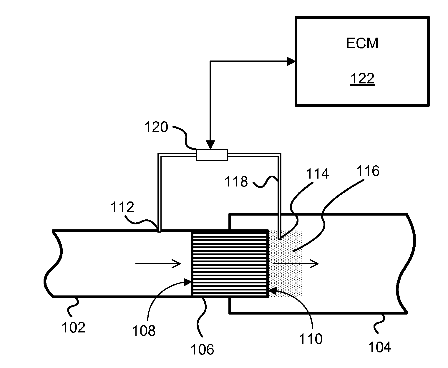
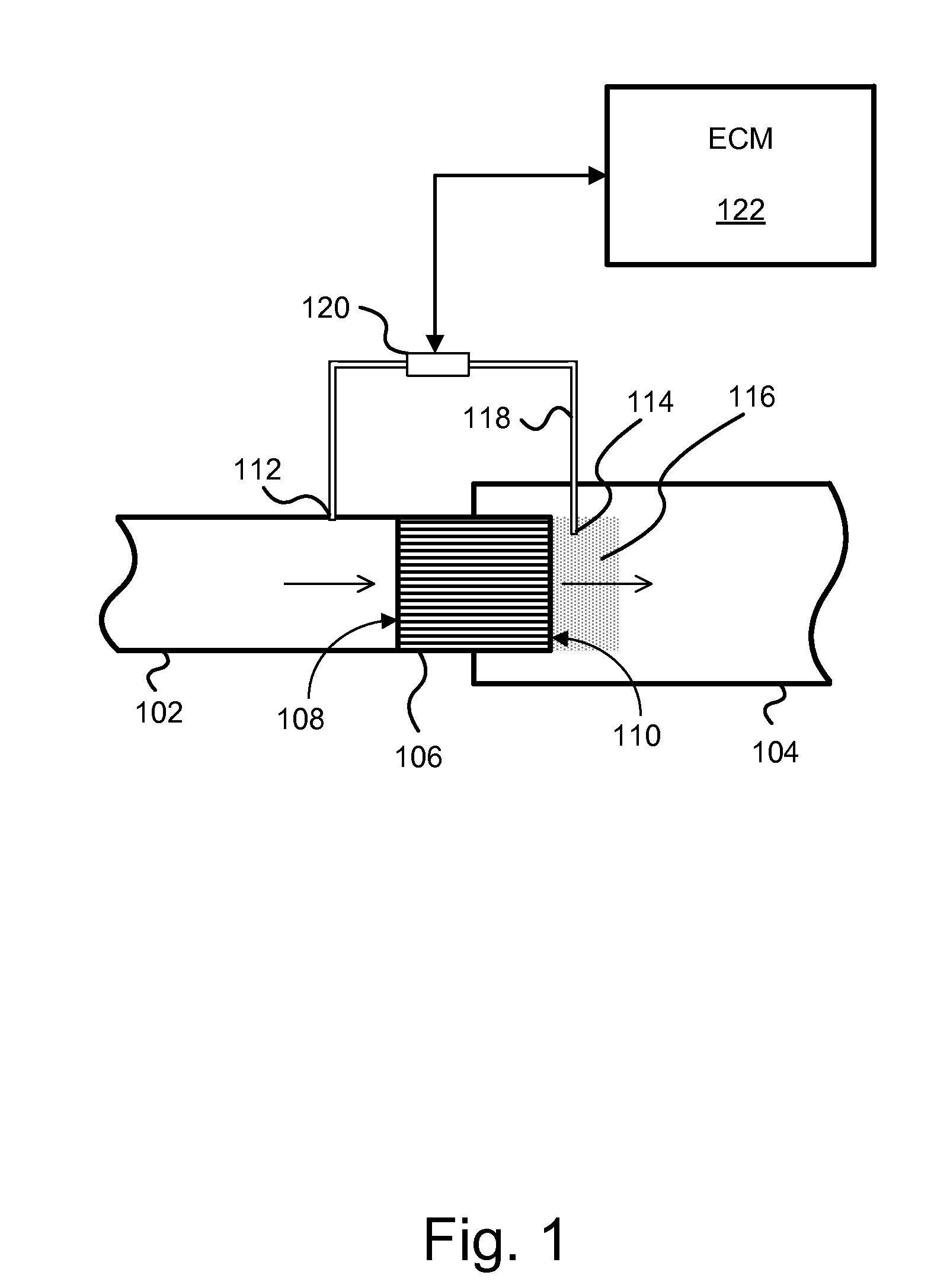
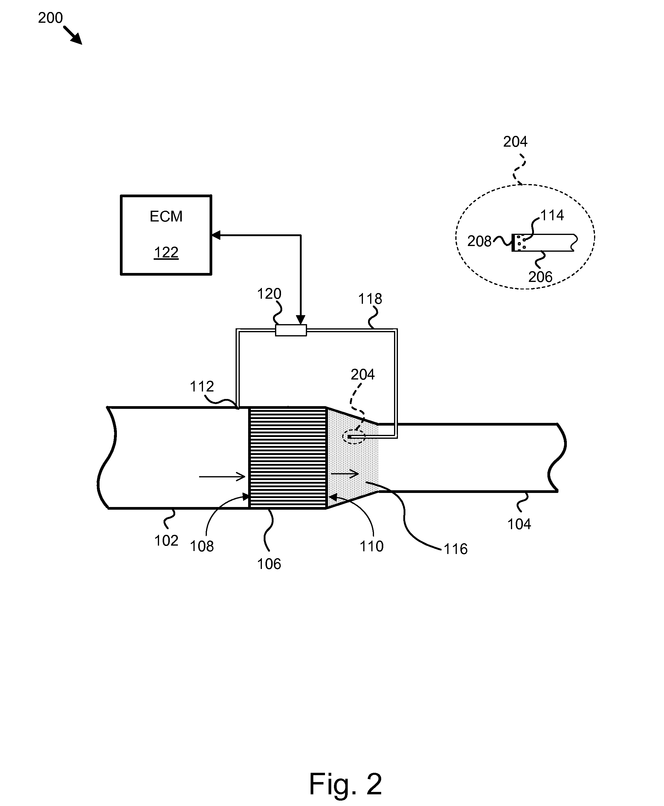
Apparatus, system, and method for differential pressure measurement across a conduit flow area change
a technology of differential pressure measurement and flow area change, applied in the direction of apparatus for force/torque/work measurement, instruments, separation processes, etc., can solve problems such as cracking or other stress related failures, temperature spikes, and large temperature gradients
- Summary
- Abstract
- Description
- Claims
- Application Information
AI Technical Summary
Benefits of technology
Problems solved by technology
Method used
Image

Examples
Embodiment Construction
[0029]It will be readily understood that the components of the present invention, as generally described and illustrated in the figures herein, may be arranged and designed in a wide variety of different configurations. Thus, the following more detailed description of the embodiments of the apparatus, system, and method of the present invention, as presented in FIGS. 1 through 6, is not intended to limit the scope of the invention, as claimed, but is merely representative of selected embodiments of the invention.
[0030]Reference throughout this specification to “one embodiment” or “an embodiment” means that a particular feature, structure, or characteristic described in connection with the embodiment is included in at least one embodiment of the present invention. Thus, appearances of the phrases “in one embodiment” or “in an embodiment” in various places throughout this specification are not necessarily all referring to the same embodiment.
[0031]Furthermore, the described features, ...
PUM
 Abstract
Description
Claims
Application Information