Pneumatic Tire

a technology of pneumatic tires and blocks, applied in the field of pneumatic tires, can solve the problems of insufficient reduction of the depth of a part inability to fulfill the function inability to reduce the depth of the three-dimensional sipe, so as to suppress the reduction in the stability of straight running, the rigidity of the block on the tire equator line side can be further improved, and the effect of improving the stability

Inactive Publication Date: 2008-06-12
BRIDGESTONE CORP
View PDF4 Cites 10 Cited by
  • Summary
  • Abstract
  • Description
  • Claims
  • Application Information

AI Technical Summary

Benefits of technology

[0012]When two or more of the cutouts are formed, since the cutout, which is closer to the tire equator line, has a length in the tire radial direction greater than the length in the tire radial direction of another cutout, the rigidity of the block on the tire equator line side can be further improved. As a result, it is possible to suppress the reduction in the stability in straight running on the dry road surface.

Problems solved by technology

Incidentally, when the length of each cutout in the tire radial direction is smaller than 50% of the length of each three-dimensional sipe in the tire radial direction, the depth of part of the three-dimensional sipe is not sufficiently reduced.
Accordingly, the rigidity of the block cannot be sufficiently improved.
On the other hand, when the length of each cutout in the tire radial direction is greater than 90% of the length of each three-dimensional sipe in the tire radial direction, it is not possible to fulfill the function of the three-dimensional sipe.
Accordingly, the starting and braking performances on snow cannot be improved.
Furthermore, when the length of the three-dimensional sipes in the tire width direction is less than 1 mm, a sufficient rigidity of the block cannot be obtained.
On the other hand, when the length is greater than 5 mm, the rigidity of the block is excessively high.
As a result, the starting and braking performances on snow cannot be improved.

Method used


Image

  • Pneumatic Tire
  • Pneumatic Tire
  • Pneumatic Tire

Examples


embodiments

[0036]Hereinafter, descriptions will be given in detail of an example of the pneumatic tire according to the present invention.

[0037]A pneumatic tire including a tread portion of the present invention (Example 1) was prepared. The pneumatic tire was attached to a wheel, and then the wheel with the pneumatic tire was mounted on a front-engine front-wheel-drive vehicle with an engine displacement of 1800 cc. The vehicle was tested to evaluate the starting performance and the braking performance is on snow as well as the stability in straight running on the dry road surface. For comparison, pneumatic tires of Comparative Example 1, Comparative Example 2 and Comparative Example 3 were also prepared, and were then tested under the same condition.

example 1

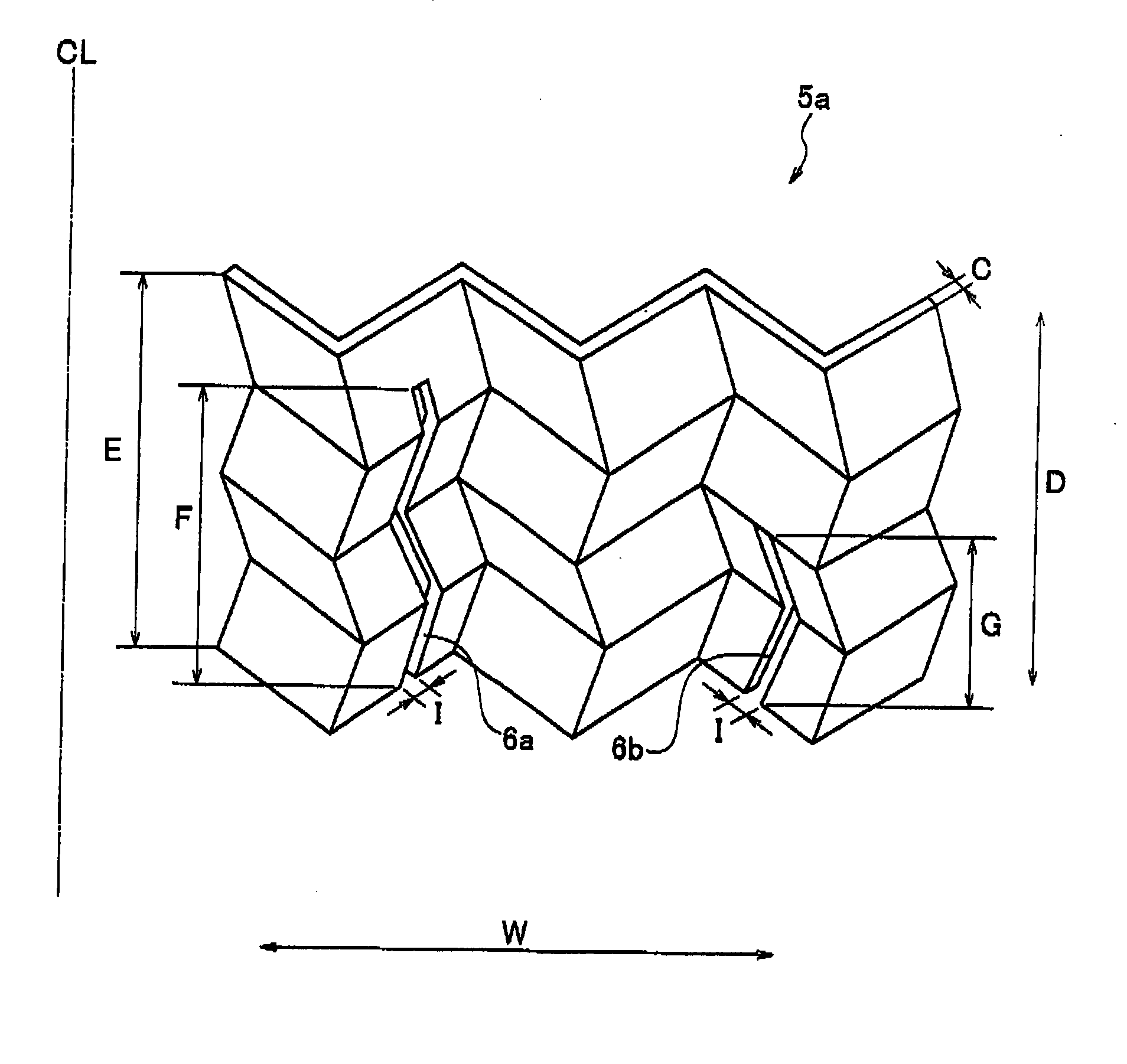
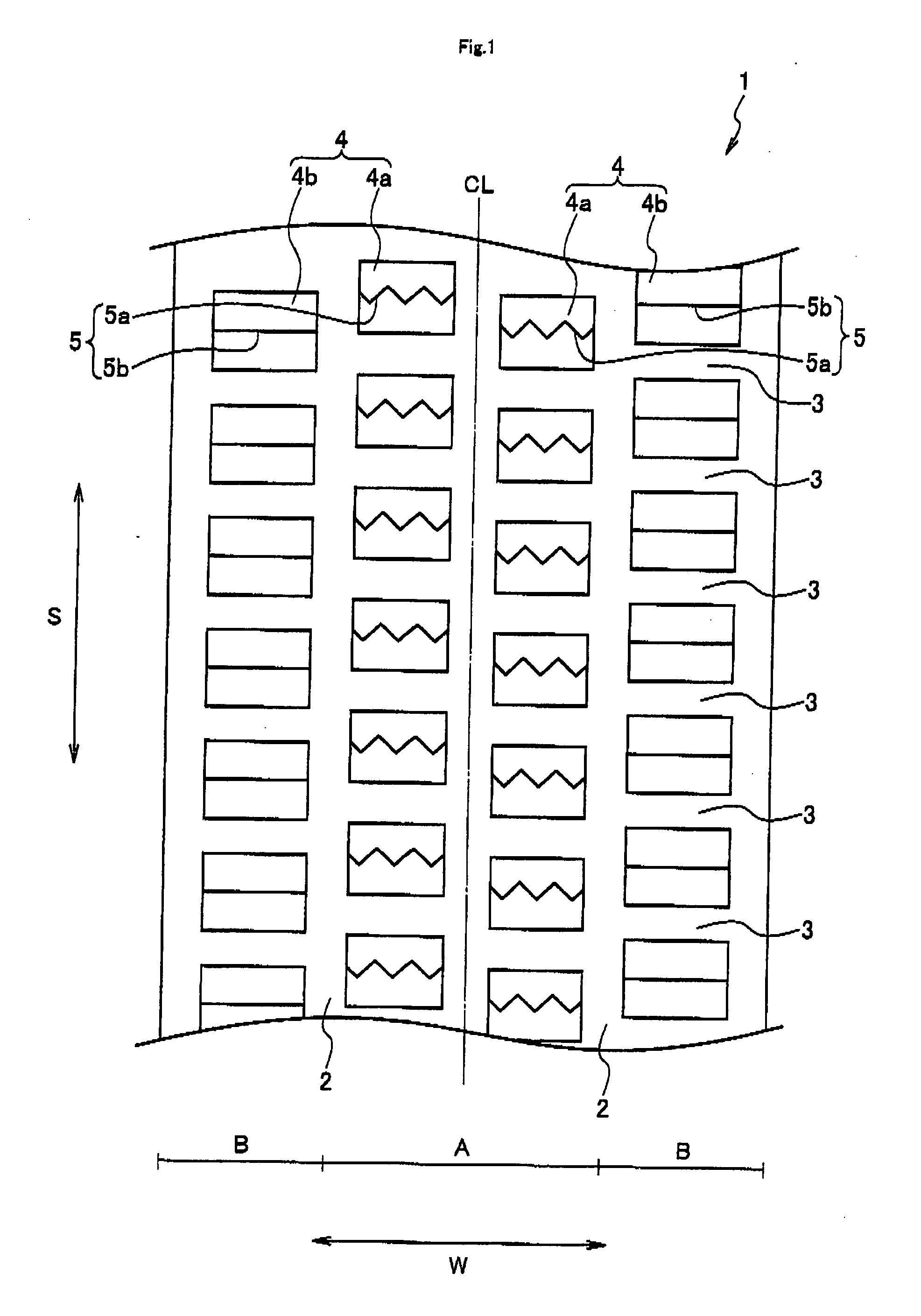
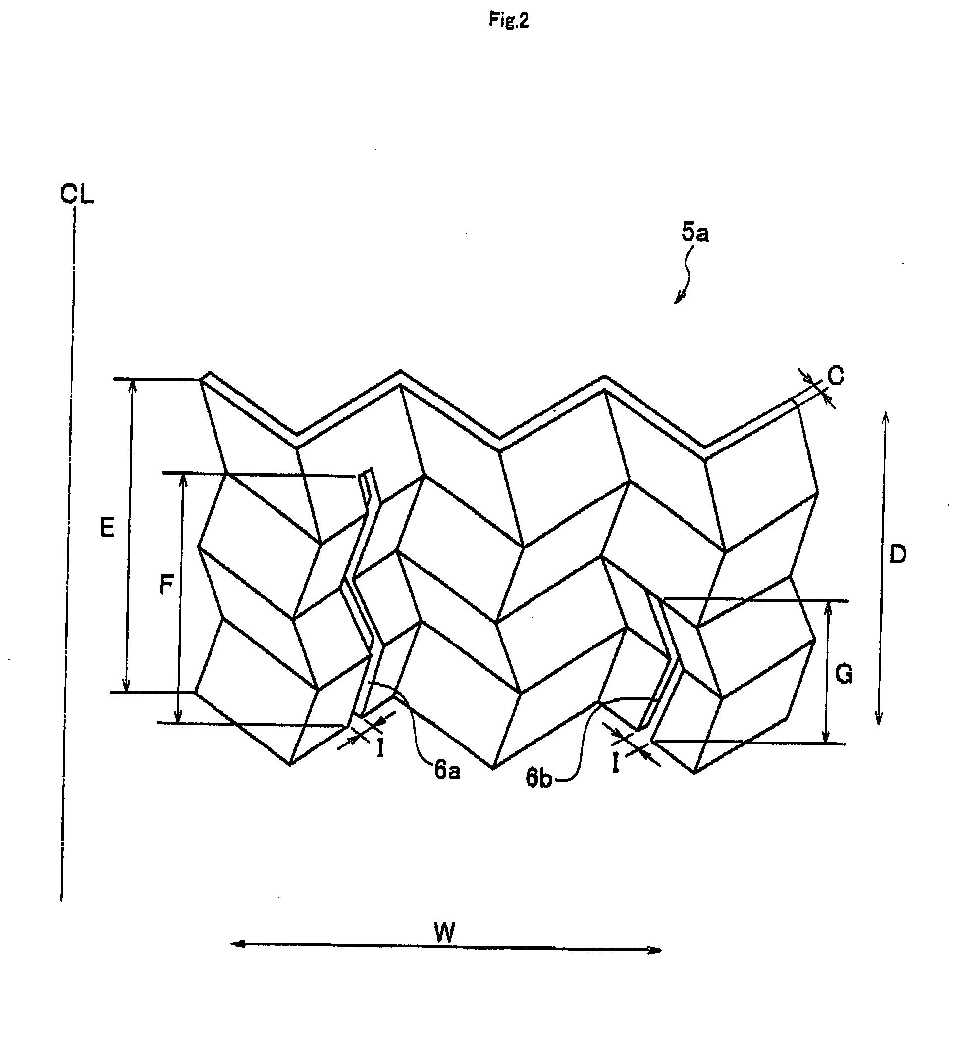
[0038]Example 1 was the pneumatic tire of the present invention. This pneumatic tire is provided with the three-dimensional sipe 5a in each of the center-region blocks 4a, and is also provided with the linear sipe 5b in each of the edge-region blocks 4b. Each of the three-dimensional sipes 5a formed respectively in the center-region blocks 4a has the shape shown in FIG. 2, a groove width of 2.0 mm and two cutouts formed therein. The depth F of the center-side cutout 6a is 5.5 mm while the depth G of the edge-side cutout 6b is 4.0 mm. The linear sipe 5b formed in the edge-region blocks 4b has a groove width of 0.7 mm.


PUM


Abstract

A pneumatic tire including a plurality of grooves which extend at least in the circumferential direction, and which are formed in a tread portion and sipes which are formed in a plurality of blocks formed by the grooves. In the pneumatic tire, the groove width of the sipe formed in each of the blocks constituting a center region of the tread portion is greater than the groove width of the sipe formed in each of the blocks constituting edge regions of the tread portion. At least the sipes formed in the blocks constituting the center region are three-dimensional sipes each having a zigzag shape extending in the width, circumferential and radial directions of the tire. Each of the three-dimensional sipes is provided with, on the inner side thereof in the tire radial direction, at least one cutout which has a length, in the tire radial direction, of 50 to 90% of the length of the three-dimensional sipe in the tire radial direction, and which has a length, in the tire width direction, of 1 to 5 mm.

Description

TECHNICAL FIELD[0001]The present invention relates to a pneumatic tire that includes a plurality of grooves extending at least in the circumferential direction in a tread portion, and that also includes a plurality of blocks formed by the grooves.BACKGROUND ART[0002]Conventionally, a pneumatic tire including sipes, which are narrow slits, in blocks formed in a tread portion has been known.[0003]In addition, in recent years, there has been a pneumatic tire including three-dimensional sipes each formed into a zigzag shape extending in the tire width direction, in the tire circumferential direction and in the tire radial direction (for example, refer to Japanese Patent Application Laid-open Publication 2004-203128).[0004]In a pneumatic tire including such three-dimensional sipes as described above, the surface of each block is divided along the tire width direction. Accordingly, although the starting and braking performances on snow are improved, the rigidity of the block is made insuf...

Claims


Application Information

Patent Timeline
Patent Type & Authority Applications(United States)
IPC IPC(8): B60C11/12
CPCB60C11/12B60C11/1218B60C2011/1286B60C2011/1213B60C11/1263Y10S152/03Y10S152/902
Inventor SAKAMAKI, YUJI
Owner BRIDGESTONE CORP
Why Eureka
Try Eureka