Well system having galvanic time release plug

Active Publication Date: 2008-06-12
HALLIBURTON ENERGY SERVICES INC
View PDF9 Cites 218 Cited by
  • Summary
  • Abstract
  • Description
  • Claims
  • Application Information

AI Technical Summary

Benefits of technology

[0008]In yet another aspect of the invention, a method of controlling fluid flow in a well system includes the steps of: obstructing flow through a passa

Problems solved by technology

However, this method of temporarily preventing flow through a passage presents problems in certain situations.
For example, if acidic fluid

Method used


Image

  • Well system having galvanic time release plug
  • Well system having galvanic time release plug
  • Well system having galvanic time release plug

Examples


Embodiment Construction

[0014]It is to be understood that the various embodiments of the present invention described herein may be utilized in various orientations, such as inclined, inverted, horizontal, vertical, etc., and in various configurations, without departing from the principles of the present invention. The embodiments are described merely as examples of useful applications of the principles of the invention, which is not limited to any specific details of these embodiments.

[0015]In the following description of the representative embodiments of the invention, directional terms, such as “above”, “below”, “upper”, “lower”, etc., are used for convenience in referring to the accompanying drawings. In general, “above”, “upper”, “upward” and similar terms refer to a direction toward the earth's surface along a wellbore, and “below”, “lower”, “downward” and similar terms refer to a direction away from the earth's surface along the wellbore.

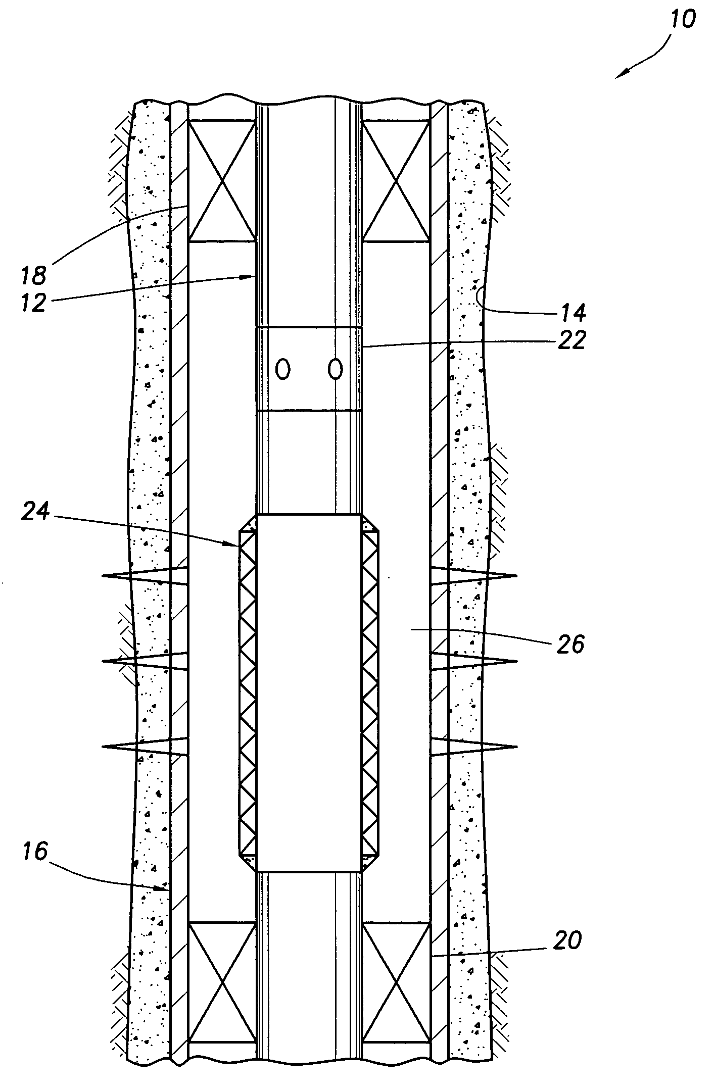
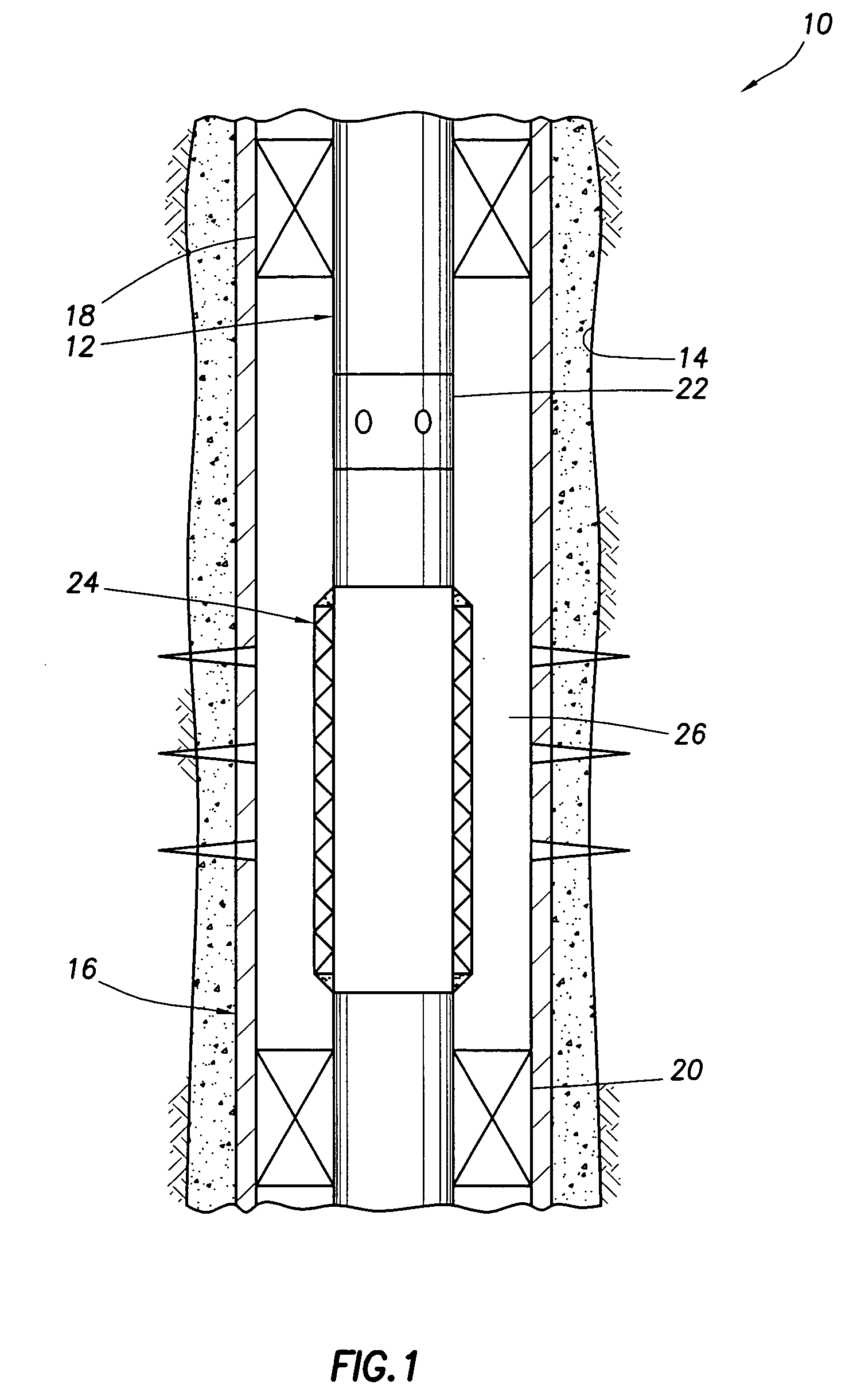
[0016]Representatively illustrated in FIG. 1 is a well system 1...


PUM


Abstract

A well system having a galvanic time release plug. A well system includes a flow passage and a flow blocking device which selectively obstructs flow through the passage, the device including an electrode in a galvanic cell. A flow blocking device for use in conjunction with a subterranean well includes a portion which delays an electrochemical reaction in a galvanic cell. A method of controlling fluid flow in a well system includes the steps of: obstructing flow through a passage using a flow blocking device which includes an electrode of a galvanic cell; and increasing flow through the passage by operation of the galvanic cell.

Description

BACKGROUND[0001]The present invention relates generally to equipment utilized and operations performed in conjunction with subterranean wells and, in an embodiment described herein, more particularly provides a well system having a galvanic time release plug.[0002]It is well known to temporarily prevent flow through a passage in a well by use of a dissolvable plug. Typically, the plug is dissolved by circulating acid to the plug. However, this method of temporarily preventing flow through a passage presents problems in certain situations.[0003]For example, if acidic fluids are to be used in the well prior to the time at which it is desired to dissolve the plug, premature dissolving of the plug could result. It will be appreciated by those skilled in the art that acid is commonly used in completion cleanup operations, and so if it is desired to delay permitting flow through a passage until after completion cleanup operations are concluded, then a plug readily dissolvable in acid shou...

Claims


Application Information

Patent Timeline
IPC IPC(8): E21B33/12
CPCE21B33/1208E21B43/088E21B33/134
Inventor FRIPP, MICHAEL L.ZHANG, HAOYUHOLDERMAN, LUKE W.FRIPP, DEBORAHSANTRA, ASHOK K.GHOSH, ANINDYA
Owner HALLIBURTON ENERGY SERVICES INC
Why Eureka
Try Eureka