
Elevated welding-type cable support system

a technology of welding-type cable and support system, which is applied in the direction of soldering apparatus, manufacturing tools,auxillary welding devices, etc., can solve the problems of long cables, affecting mobility, and often serving as impediments, so as to facilitate cable storage

Active Publication Date: 2008-06-12
ILLINOIS TOOL WORKS INC
View PDF15 Cites 95 Cited by
  • Summary
  • Abstract
  • Description
  • Claims
  • Application Information

AI Technical Summary

Benefits of technology

[0009]The present invention overcomes the aforementioned drawbacks by providing a welding-type cable management system that allows an operator to interact with the cable in a more ergonomic position and, thus, encourages the operator to utilize the cable management system. Furthermore, the present invention provides a welding-type cable management system that facilitates storage of a cable in a relatively large coil that is less likely to cause premature wearing of the cable.

Problems solved by technology

While a lengthy cable is often included to provide an operator with a large amount of latitude, an overly lengthy cable can hinder mobility.
That is, during operation, the slack cable rests about the area where the operator is located and can present an obstacle to mobility.
Furthermore, the cable often serves as an impediment to easy storage and transportation of the welding-type device.
Unfortunately, even when these cable and / or torch storage and management systems are included, in operation, they often go unused.
Operators often forego the process of storing the cable and torch after each use.
Even more likely, operators fail to use these cable management systems during operation of the welding-type device.
In addition, even when these cable management systems are used, they have the potential to cause damage to the cable.
The stress placed on the cable when being wrapped in a small coil, increases the risk that the liner of the cable will become kinked with respect to the conductive, gas flow paths, and / or feed ability of the wire located therein.
Over time, these stresses can even cause premature wear on the cable.
Accordingly, even when these cable management systems are properly used by operators to protect the cable and gun or torch from accidental damage, the cable management systems have the potential to induce premature failure of the cable.

Method used


Image

  • Elevated welding-type cable support system
  • Elevated welding-type cable support system
  • Elevated welding-type cable support system

Examples


Embodiment Construction

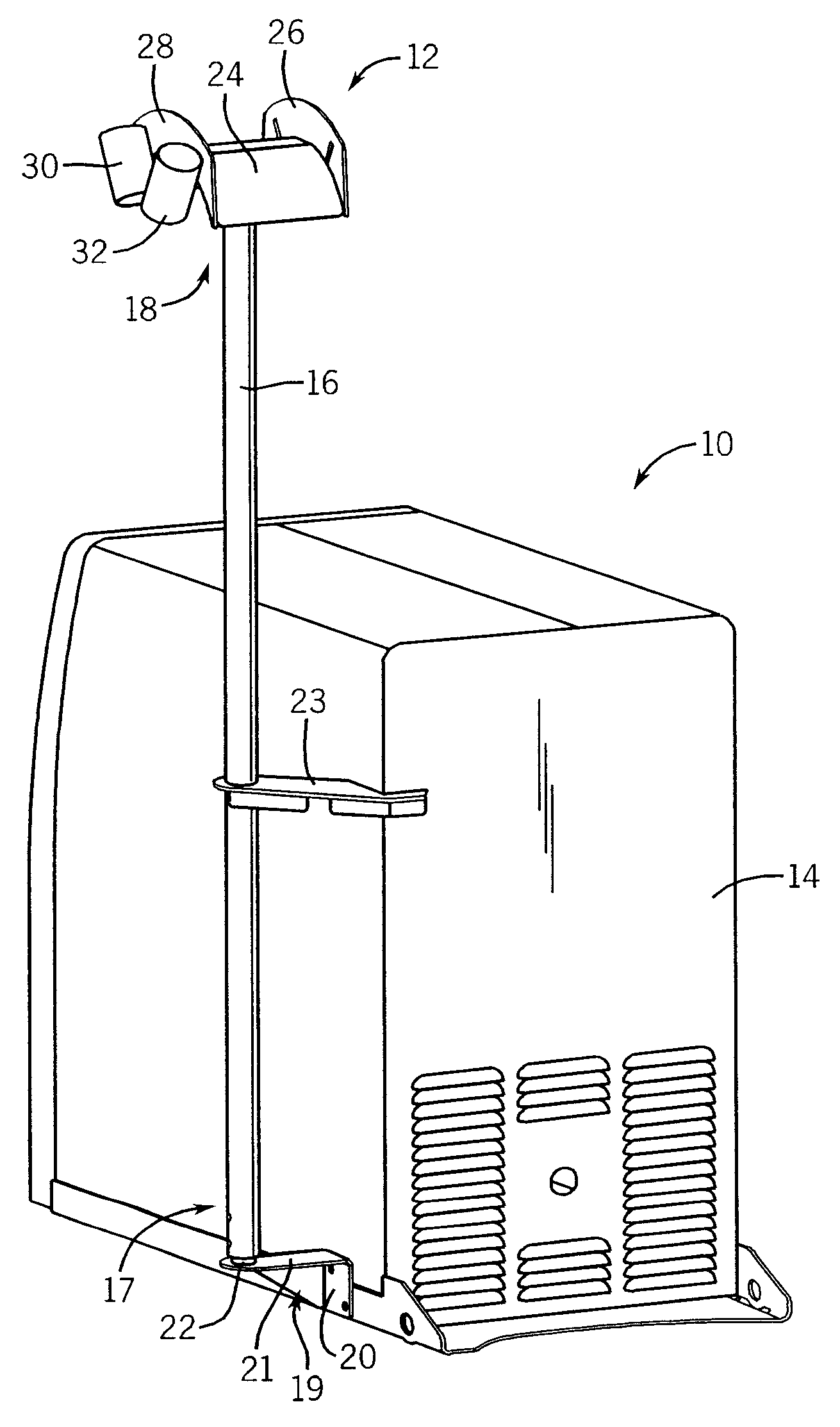
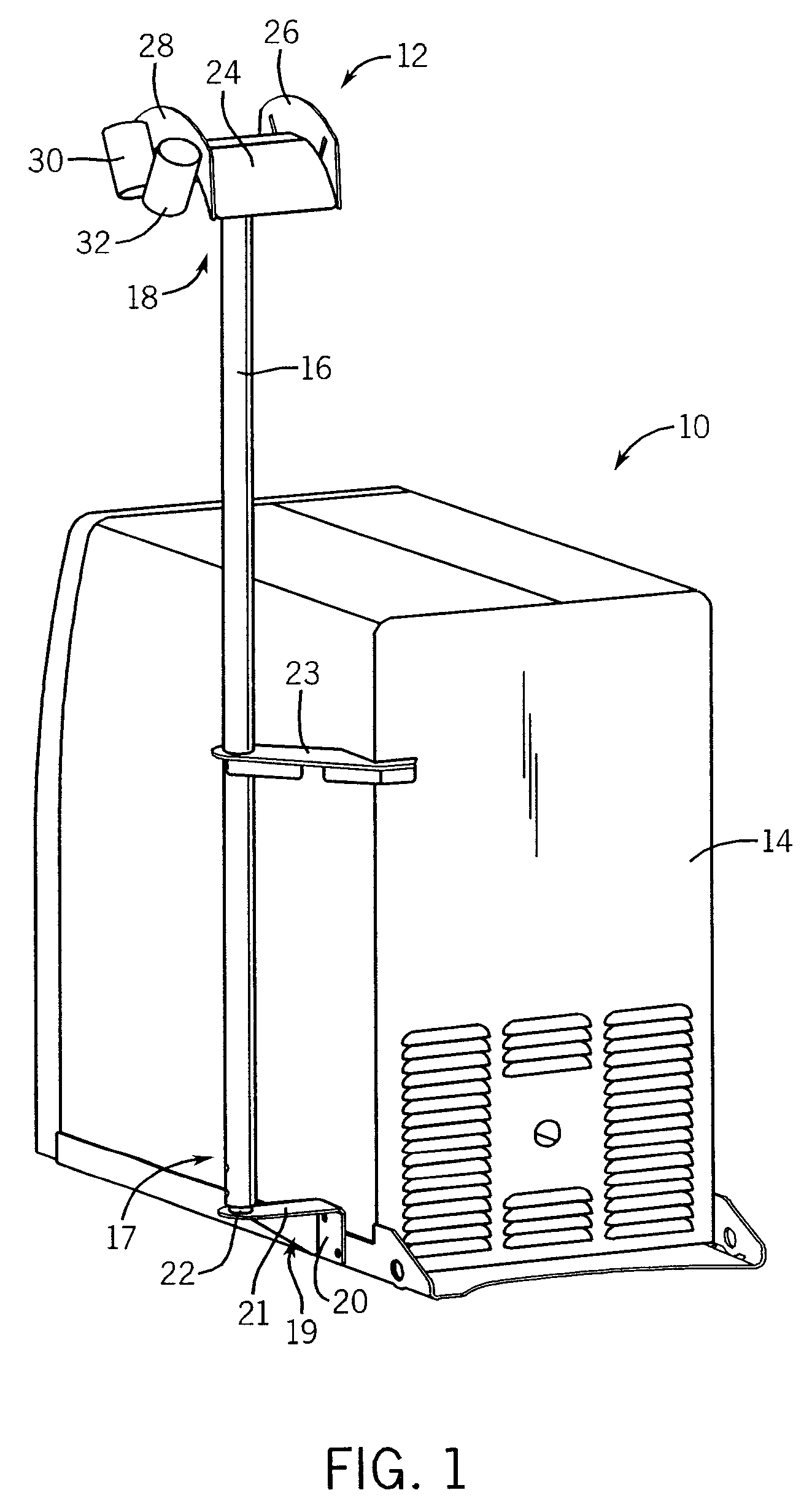
[0018]Referring now to FIG. 1, a welding-type system 10 and associated cable management system 12 are shown. The welding-type system 10 includes a housing 14 that encases the components of a power source that is designed to deliver welding-type power. Reference to welding-type systems, welding-type devices, and welding-type power is used to describe systems and power that have operational characteristics similar to welding systems, such as induction heating systems, plasma cutting systems, and the like.

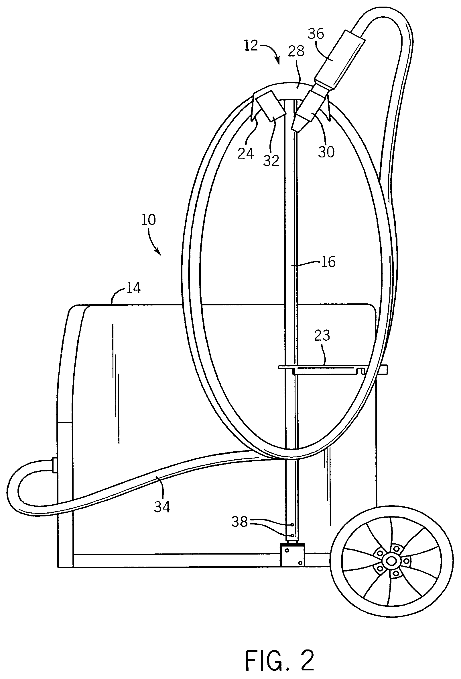
[0019]The cable management system 12 includes a support column 16 that is engaged with the housing 14 of the welding-type system 10 at a first end 17 through a mounting flange 19 and extends to a second end 18 that terminates above the housing 14 of the welding-type system 10. The mounting flange 19 includes a mounting face 20 that is fixed to the housing 14 and a support platform 21 forming a substantially planar surface that extends from the mounting face 20. A connection shaft 22 e...


PUM

PropertyMeasurementUnit
Lengthaaaaaaaaaa

Abstract

A cable management system for a welding-type system includes a support column extending in a first direction from a first end supported by a welding-type device to a second end arranged above the welding-type device. The cable management system also includes a cable support arranged on the second end of the support column that extends in a second direction substantially transverse to the first direction. Accordingly, a portion of the cable support extends away from the welding-type device to allow a cable supported thereon to extend below the cable support and proximate to the welding-type device.

Description

REFERENCE TO RELATED APPLICATIONS[0001]Not applicable.STATEMENT REGARDING FEDERALLY SPONSORED RESEARCH OR DEVELOPMENT[0002]Not applicable.BACKGROUND OF THE INVENTION[0003]The present invention relates generally to welding cable management systems and, more particularly, to a system for supporting and storing a welding-type cable and welding-type gun in an elevated position.[0004]Welding-type systems, such as welders, plasma cutters, and induction heaters, typically include a gun or torch that is tethered to a power supply through a cable. In many cases, the cable is designed to span many feet to enable an operator to move the gun or torch to a variety of work areas without needing to move the power supply. While a lengthy cable is often included to provide an operator with a large amount of latitude, an overly lengthy cable can hinder mobility. That is, during operation, the slack cable rests about the area where the operator is located and can present an obstacle to mobility. Furth...

Claims


Application Information

Patent Timeline
IPC IPC(8): B23K37/00
CPCB23K9/32B23K9/328B23K9/123
Inventor ERTMER, JONATHAN R.ROEHL, CHRIS J.BREITBACH, JOHN C.YUNK, THOMAS G.
Owner ILLINOIS TOOL WORKS INC
Learn More