

Display device and method of producing the same
a display device and display technology, applied in the field of display devices, can solve the problems of affecting crystallization, lowering the display quality of the active matrix display device, and high resistance of the polycrystalline semiconductor film, so as to achieve the effect of improving the display quality of the display devi
- Summary
- Abstract
- Description
- Claims
- Application Information
AI Technical Summary
Benefits of technology
Problems solved by technology
Method used
Image

Examples
embodiment 1
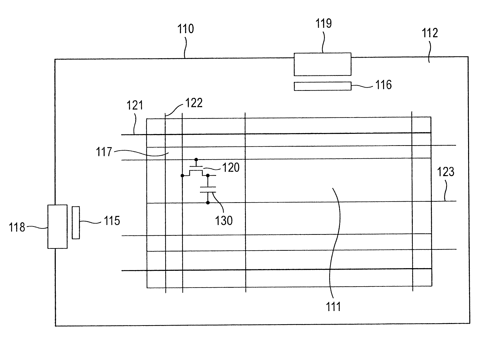
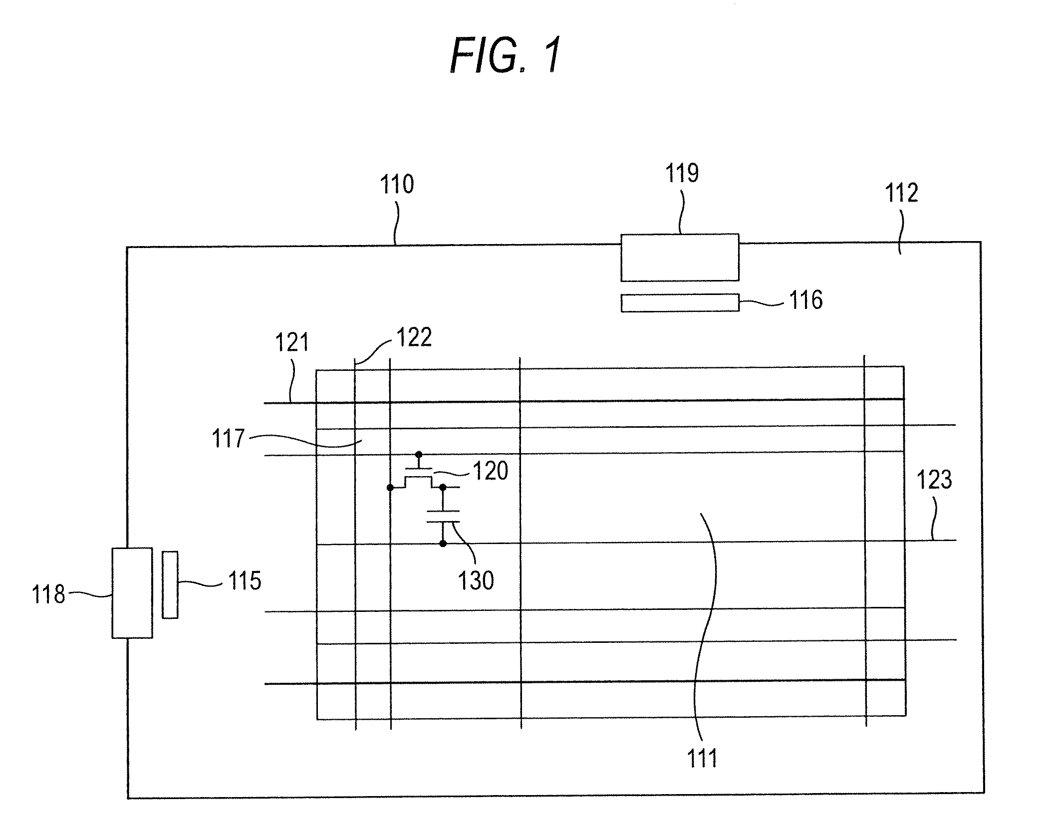
[0031]First, a TFT substrate constituting the display device of the invention will be described. FIG. 1 is a front view showing the configuration of a TFT substrate used in the display device. As the display device of the invention, a liquid crystal display device will be exemplarily described. However, this is for illustrative purpose only. Alternatively, for example, a flat panel display device such as an organic EL display device may be used.
[0032]The display device of the invention has the TFT substrate 110. For example, the TFT substrate 110 is a TFT array substrate. In the TFT substrate 110, a display region 111, and a frame region 112 which surrounds the display region 111 are disposed. In the display region 111, plural gate wirings (scan signal lines) 121 and plural source wirings (display signal lines) 122 are formed. The plural gate wirings 121 are disposed in parallel to one another. Similarly, the plural source wirings 122 are disposed in parallel to one another. The gat...
embodiment 2
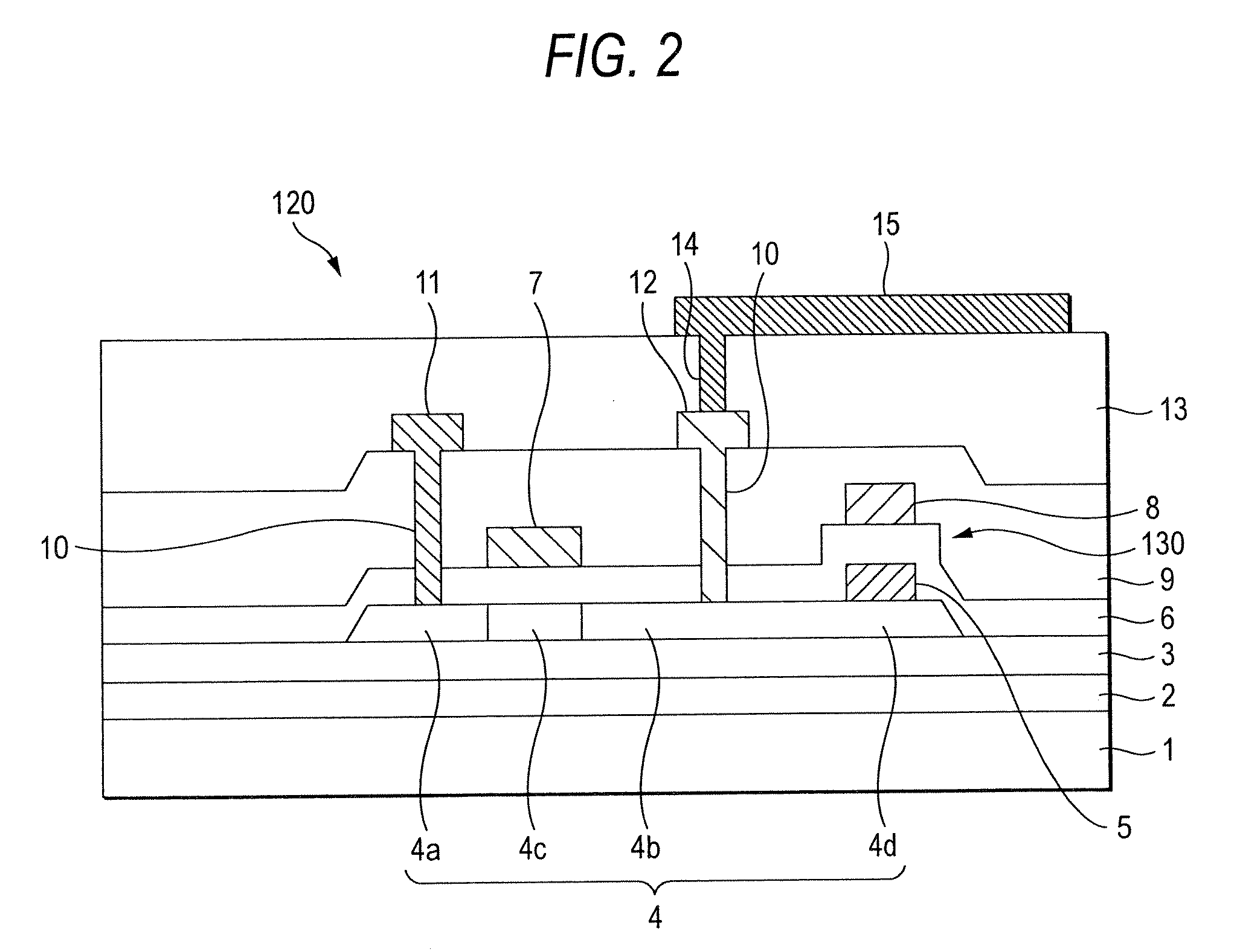
[0067]In Embodiment 1, the conductive film was formed only on the storage capacitor lower portion which is a semiconductor layer for forming the lower electrode of the storage capacitor. Embodiment 2 is characterized in that the conductive film which is to be formed on the semiconductor layer is formed not only in the storage capacitor, but also in a portion which is contacted to the drain electrode in the drain region, and that which is contacted to the source electrode in the source region. FIG. 8 is a sectional view of the TFT 120 and the storage capacitor 130 in a display device of Embodiment 2.
[0068]Referring to FIG. 8, the conductive film 5 is extended from the storage capacitor 130 so as to be formed not only therein, but also on the drain region 4b of the TFT 120. Furthermore, the conductive film is formed also on the source region 4a. Namely, as the conductive film 5, there are not only the conductive film formed as the storage capacitor 130, but also the conductive film 5 ...
embodiment 3
[0071]FIG. 9 is a sectional view of the TFT 120 and the storage capacitor 130 in the display device of Embodiment 3. Embodiment 3 is different from Embodiments 1 and 2 in that the first contact holes 10 formed in the gate insulating film 6 and the first interlayer insulating film 9, and the second contact hole 14 formed in the second interlayer insulating film 13 are overlappingly formed at a substantially same position, and that the pixel electrode 15 and the conductive film 5 are directly connected to each other without passing through the drain electrode 12. The production method is different only in the existence / nonexistence of the drain electrode 12, and the timing of the formation of the first contact holes 10. In Embodiment 2, the first contact holes 10 are opened after the first interlayer insulating film 9 is formed. By contrast, Embodiment 3 is characterized in that, after the second interlayer insulating film 13 is formed, the second contact hole 14 and the first contact...
PUM
 Abstract
Description
Claims
Application Information