Drill Chuck Locked Through An Inclined Wedge Surface
a technology of inclined wedge and drill bit, which is applied in the direction of chucks, mechanical equipment, manufacturing tools, etc., can solve problems such as production obstacles
- Summary
- Abstract
- Description
- Claims
- Application Information
AI Technical Summary
Benefits of technology
Problems solved by technology
Method used
Image
Examples
first embodiment
[0110
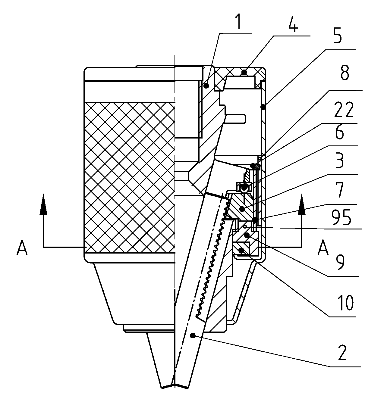
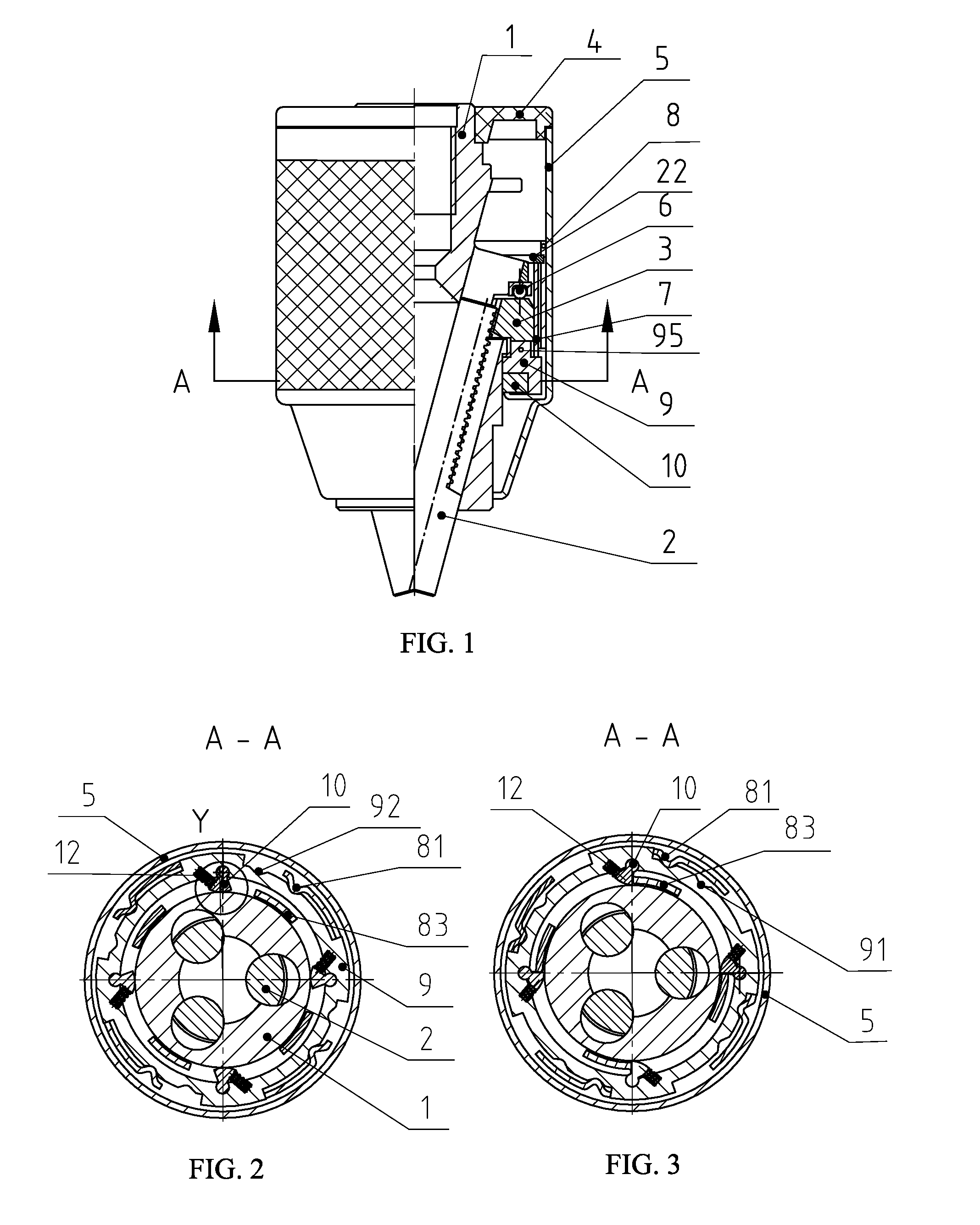
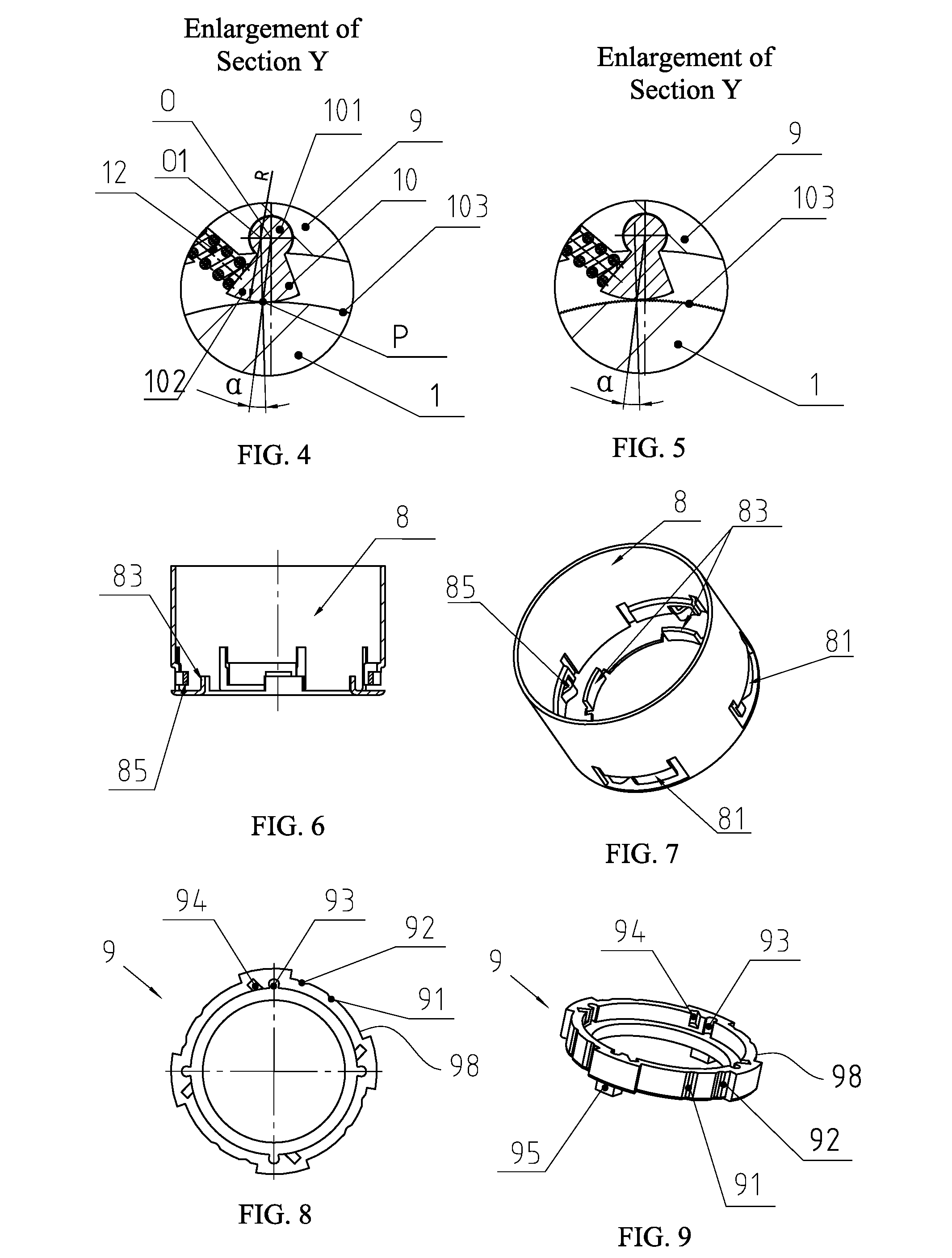
[0111]FIG. 1 to 9 show the first embodiment of the drill chuck locked through an inclined wedge surface according to the present invention. As shown in FIG. 1, the drill chuck locked through an inclined wedge surface comprises a drill body 1, jaws 2, a nut 3, a rear sleeve 4, an outer sleeve 5, a bearing assembly 6, a nut sleeve 7, a control sleeve 8, a wedge block type lock ring 9, a wedge block 10, an elastic member 12, and a snap spring 22. The drill body 1 is provided with three inclined holes with their axes intersecting at one point in the axis of the drill body. The three inclined holes of the drill body 1 are respectively mounted with movable jaws 2 which are provided on one side with partial threads and are provided on the other side with ridge which is parallel to the axis of the drill body 1 and is used for gripping the tool handle. The nut 3 is fitted around the drill body 1 and has female thread adapted for engaging with the partial thread of the jaw 2, such that t...
second embodiment
[0121
[0122]FIG. 10 to 22 show the second embodiment of the drill chuck locked through an inclined wedge surface according to the present invention which has the difference from the first embodiment that the wedge block type lock ring 9 is placed at the rear portion of the drill body 1.
[0123]Referring to FIGS. 10, 13 and 14, it can be found that the outer sleeve 5 has a key groove 52 and a hole 53 in the inner wall. The front cover 20, fitted around the front portion of the drill body 1, is axially fixed on the drill body through a clip ring 21 and provided thereon with a key 201 cooperating with the hole 53, therefore the front cover 20 and the outer sleeve 5 are connected together through the cooperation between the key 201 and the key hole 53.
[0124]Referring to FIGS. 15 and 16, it can be found that the control sleeve 8 is provided at the lower end with plural drive keys 82 which cooperate insertedly with the key groove 52 of the outer sleeve 5 (as shown in FIG. 12), therefore, the...
third embodiment
[0129
[0130]FIG. 23 to 33 show the third embodiment of the drill chuck locked through an inclined wedge surface according to the present invention in which the locking is achieved by a rolling body and the inclined wedge surface.
[0131]Referring to FIGS. 28 and 29, it can be found that the rolling body type lock ring 19 is rotatably mounted around the drill body 1 and provided thereon with plural force-transfer keys 193 for connecting insertedly with the drive groove 32 of the nut 3, so as to simultaneously rotate with the nut 3. The rolling body type lock ring 19 is provided in the inner side with elastic member mounting positions 94 and inclined wedge surfaces 96, wherein the elastic member mounting position 94 is used for mounting an elastic member 12, such as a spring, which biases against a rolling body 11 provided on one side of the elastic member 12, i.e. applies an elastic force on the rolling body 11. The rolling body type lock ring 9 is provided on the outer side with the dr...
PUM
 Abstract
Description
Claims
Application Information
 - R&D
- Intellectual Property
- Life Sciences
- Materials
- Tech Scout
- Unparalleled Data Quality
- Higher Quality Content
- 60% Fewer Hallucinations
Browse by: Latest US Patents, China's latest patents, Technical Efficacy Thesaurus, Application Domain, Technology Topic, Popular Technical Reports.
© 2025 PatSnap. All rights reserved.Legal|Privacy policy|Modern Slavery Act Transparency Statement|Sitemap|About US| Contact US: help@patsnap.com


