Inkjet printing apparatus and driving control method

a technology of driving control and printing apparatus, which is applied in the direction of printing and other printing apparatus, can solve the problems of reducing image quality, affecting the accuracy of printing, etc., and achieves the effect of high precision

Inactive Publication Date: 2008-06-12
CANON KK
View PDF7 Cites 10 Cited by
  • Summary
  • Abstract
  • Description
  • Claims
  • Application Information

AI Technical Summary

Benefits of technology

[0034]The present invention has been made in light of the problems described above. In particular, a feature of the present invention is to provide an inkjet printing apparatus and a method for adjusting registration of landing points of droplets capable of adjusting registration between print dots with a high precision without provision of means for inputting multiple driving signals to printing elements in the same nozzle array.

Problems solved by technology

However, these methods cannot adjust registration between landing points of nozzles in the same array because they shift landing points by moving nozzle arrays to shift the print starting position.
During development aimed at reducing droplet size and increasing printing speed, a new kind of problem has arisen associated with such smaller droplet sizes.
The change of the discharge direction changes the landing points of ink droplets both in the scanning direction of the printhead and in the direction in which nozzles are arranged, which of course results in degradation of image quality.
Moreover, it has been shown that if the time-divisional driving stated above is performed, misregistration occurs between the landing points of ink droplets discharged from nozzles in the first driven block and the landing points of ink droplets discharged from nozzles in the last driven block.
Therefore, particularly misregistration of landing points in the same nozzle array in the scanning direction of the printhead increases because misregistration of landing points caused by the time-divisional driving is combined with misregistration of landing points caused by the air resistance.
Therefore, it is becoming difficult to fine-adjust landing points simply by a conventional method of adjusting registration of landing points on a nozzle-array basis.
However, the number of nozzles and varieties of ejectable droplet sizes required of printheads are increasing year after year whereas competition to keep prices of inkjet printers down is intensifying.
While it is possible to introduce the technique described above to relatively expensive printers, introduction of the technique to low-cost printers is difficult because the technique requires an increased number of driving signal lines to printheads and as many drive timing circuits as the number of printheads, which increase the complexity and costs of the system.

Method used


Image

  • Inkjet printing apparatus and driving control method
  • Inkjet printing apparatus and driving control method
  • Inkjet printing apparatus and driving control method

Examples


first exemplary embodiment

[0092]A first exemplary embodiment will be described below in which the present invention is applied to an inkjet printing apparatus having the configuration described above.

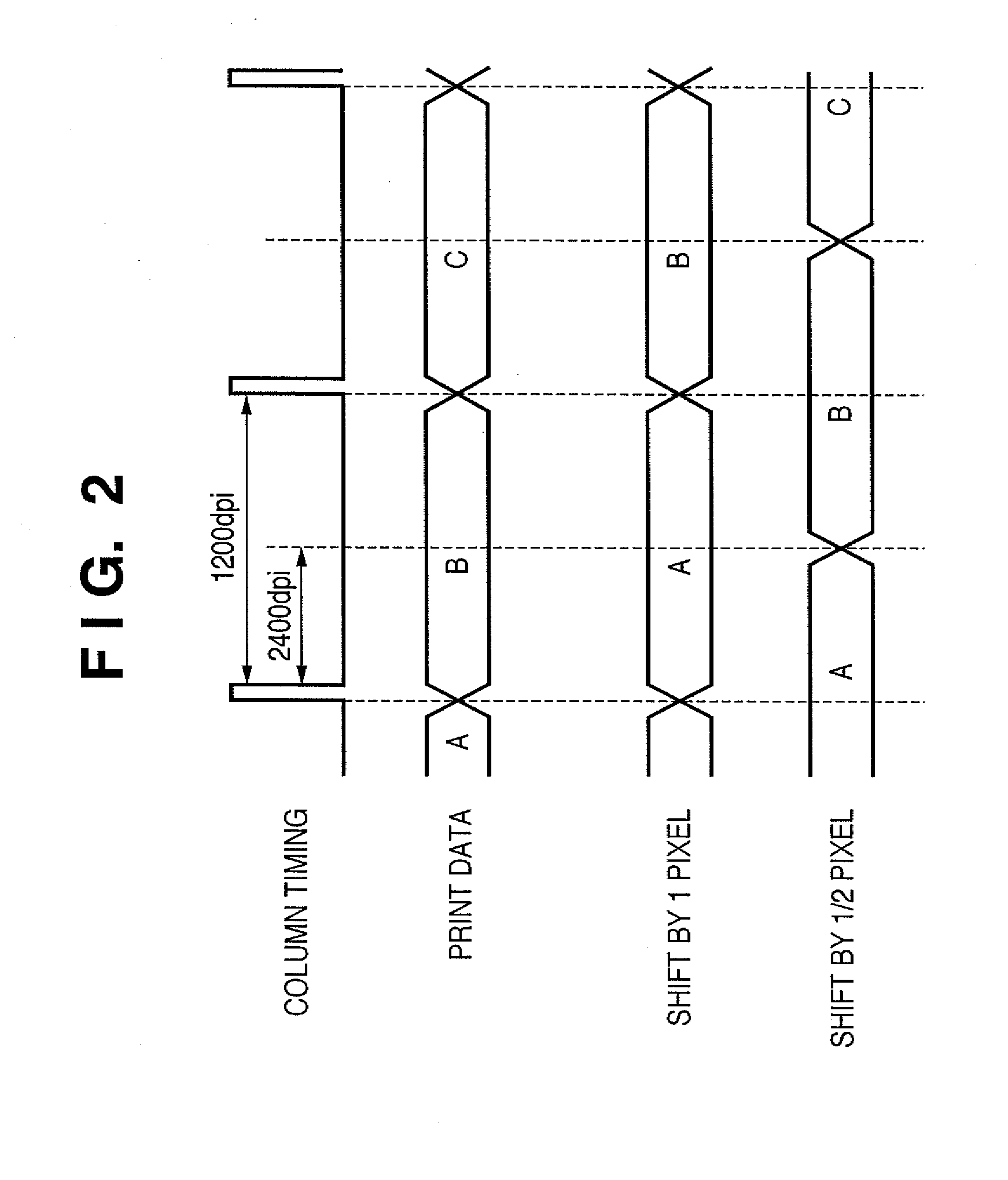
[0093]The printing apparatus in the first exemplary embodiment includes a printhead having two types of nozzles that discharge the same amount of ink but have different discharge characteristics, and has a printing mode in which the two types of nozzles are driven at the same timing (column timing) in the same main scanning direction for printing. The difference of discharge characteristics is differences of discharge speed.

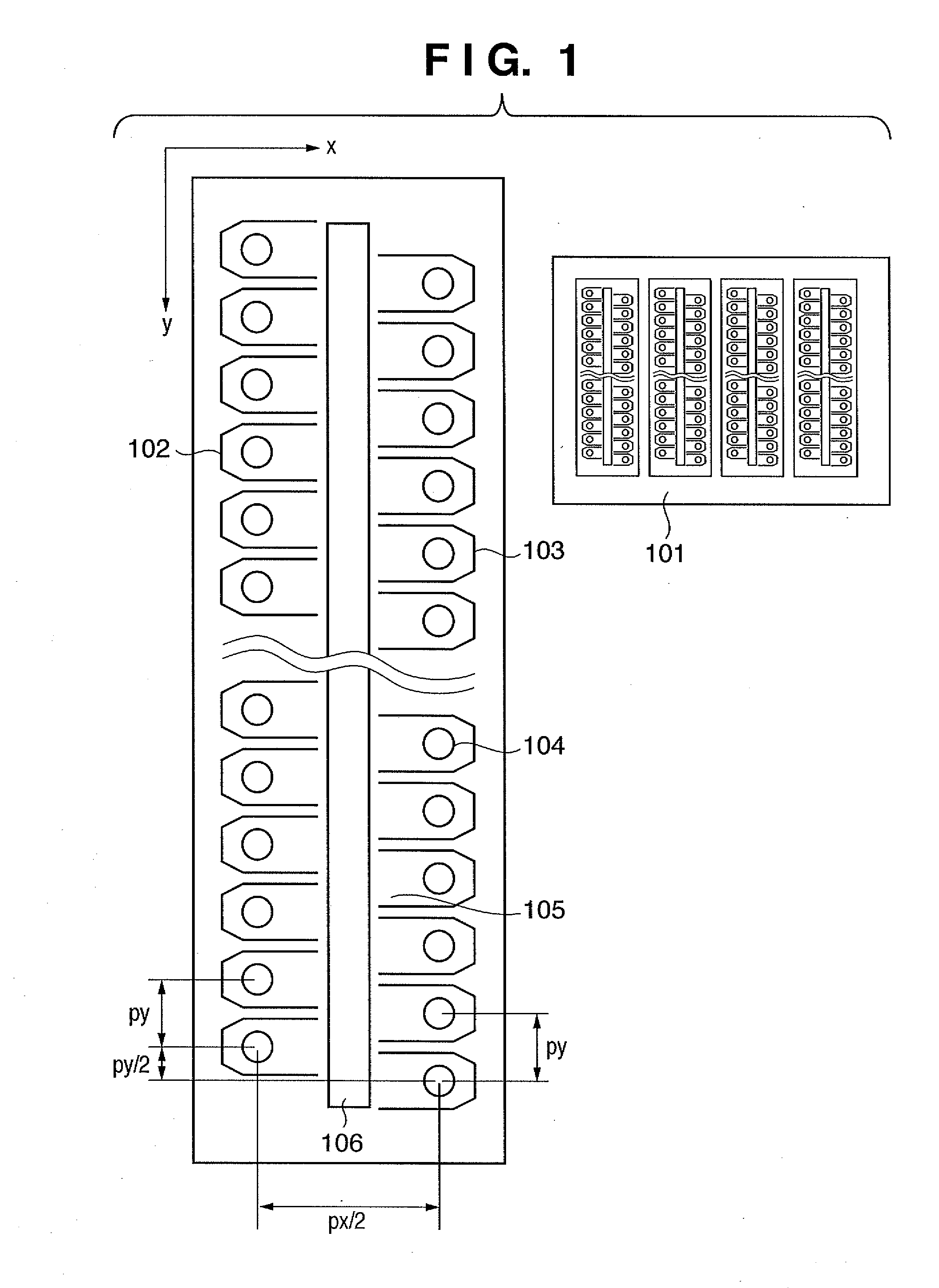
[0094]FIG. 6 shows exemplary nozzle arrays of a printhead 101 of the inkjet printing apparatus according to the first exemplary embodiment. The printhead 101 includes multiple nozzle arrays. Nozzle array 102 to the left of an ink supply path 106 is an even-numbered nozzle array in which an even number is assigned to each nozzle for convenience. Nozzle array 102 consists of nozzle groups 702A ...

second exemplary embodiment

[0108]A second exemplary embodiment of the present invention will be described below.

[0109]The printing apparatus of the second exemplary embodiment includes a printhead having two types of nozzle groups that discharge different amounts of ink, and has a print mode in which the two types of nozzle groups are driven at the same timing (column timing) in scanning by the same printhead for printing.

[0110]FIG. 12 shows exemplary arrays of nozzles of the printhead 101 having multiple nozzle arrays 102, 103. Large-diameter nozzle groups 1302A, 1303A that discharge a larger amount of ink and are used for printing larger print dots and small-diameter nozzle groups 1302B, 1303B that discharge a smaller amount of ink and are used for printing smaller print dots are disposed in the nozzle arrays 102, 103. The two types of nozzles that have a smaller diameter and a larger diameter are arranged in staggered fashion in the two nozzle arrays 102, 103. Even-numbered nozzle array 102 (nozzle groups ...

third exemplary embodiment

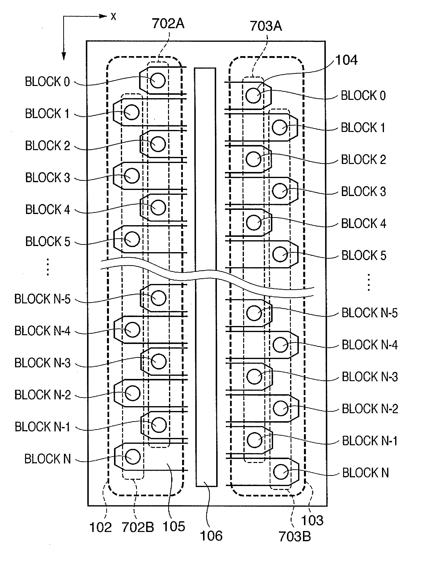
[0123]A printhead used in a third exemplary embodiment has the same nozzle arrays as in the printhead described above and shown in FIG. 6. The configurations of nozzles and signals are the same. In particular, even-numbered nozzle arrays and odd-numbered nozzle arrays are arranged at pitches (approximately 21.2 μm) corresponding to 1200 dpi and each nozzle group includes 128 nozzles. In total, 512 nozzles are provided.

[0124]The printhead in the third exemplary embodiment is divided into eight driving blocks for eight nozzles. Blocks 0 to 7 are driven in a set order to discharge ink droplets. The even-numbered and odd-numbered nozzle arrays are connected to a common driving signal line. Ink is supplied from an ink supply path 106 through each ink channel 105 associated with each nozzle 104.

[0125]Printing performed using the printhead will be described below.

[0126]When a nozzle array 102 is driven at the same timing in one printing scan, the speed at which ink droplets are discharged ...


PUM


Abstract

In a configuration in which a printhead including a plurality of first printing elements for discharging ink droplets and a plurality of second printing elements for discharging ink droplets larger than ink droplets discharged by the first printing elements is used, the first and second plurality of printing elements are divided into multiple blocks in such a manner that the first printing elements belong to one block and the second printing elements belong to another block. The blocks are individually driven in a time-divisional manner. In the time-divisional driving, the block consisting of the plurality of first printing elements is driven first and then the block consisting of the second printing elements is driven.

Description

BACKGROUND OF THE INVENTION[0001]1. Field of the Invention[0002]The present invention relates to an inkjet printing apparatus and a driving control method which enable registration adjustment for preventing a relative misregistration between droplet landing points of printing elements of a printhead.[0003]2. Description of the Related Art[0004]There are various printing apparatuses, including printing means provided in printers, copying machines, and facsimiles for printing images and other objects and printout devices used with multifunctional electronic apparatuses such as computers and word processors or workstations. These printing apparatuses are designed to print images and other objects on printing media such as paper and plastic film in accordance with image information.[0005]Such printing apparatuses can be classified by printing method as inkjet, wire dot-matrix, thermal, laser-beam and other printing apparatuses.[0006]Among these printing apparatuses, inkjet printing appa...

Claims


Application Information

Patent Timeline
Patent Type & Authority Applications(United States)
IPC IPC(8): B41J29/38
CPCB41J2/04505B41J2/04543B41J2/04573B41J2/0458B41J2002/14475B41J2/04593B41J2/15B41J2/2128B41J2/04581
Inventor YAMAGUCHI, HIROMITSUSHIBATA, TSUYOSHI
Owner CANON KK
Why Eureka
Try Eureka