Ink cartridge attachment/detachment device, recording apparatus, liquid ejection apparatus, and liquid container

a technology of ink cartridges and attachment devices, which is applied in printing, roofing, construction, etc., can solve the problems of not providing the large pressing force required to cope with an ink cartridge unit of a single package, imposing a natural force on the ink jet printer, and unable to apply such a large pressing for

Inactive Publication Date: 2008-06-12
SEIKO EPSON CORP
View PDF20 Cites 9 Cited by
  • Summary
  • Abstract
  • Description
  • Claims
  • Application Information

AI Technical Summary

Benefits of technology

[0013]According to the first aspect, since the lever arm, for which a comparatively long distance can be obtained between the operating point and the fulcrum, is employed, a comparatively large lever ratio can be obtained. Therefore, since by applying the leverage principle very little power is required to produce a large pressing force, even a single package type ink cartridge unit can be easily loaded or removed.
[0074]According to this arrangement, since the contact portion and the engagement portion are located on the face of the case, which face is substantially in parallel to the direction in which the liquid container is inserted, and is opposed to the slider, the slider can be easily brought in contact with the contact portion when the liquid container is inserted.

Problems solved by technology

Such a large pressing force can be exerted so long as the ink cartridge is loaded vertically; however, when the ink cartridge is to be slid in a direction other than the vertical direction during the loading process, an unnatural force is also imposed on the ink jet printer.
Thus, the application of such a large pressing force is practically impossible.
However, this device is one developed for the loading of ink cartridges for individual colors, and does not provide the large pressing force required to cope with an ink cartridge unit of a single package type wherein ink cartridges for a plurality of colors are integrally formed.
Further, if a cartridge attachment / detachment lever and a link plate provided for each of the color ink cartridges, the number of parts would be increased, and accordingly, the costs for parts would be higher.
Otherwise, a gap would appear between the ink cartridge and the flow path member, and contact points provided for the ink cartridge and the flow path member would be shifted, making it impossible to detect the amount of ink remaining.
Furthermore, a positional shifting of the contact points may also occur due to variances in the size tolerances for the parts.

Method used


Image

  • Ink cartridge attachment/detachment device, recording apparatus, liquid ejection apparatus, and liquid container
  • Ink cartridge attachment/detachment device, recording apparatus, liquid ejection apparatus, and liquid container
  • Ink cartridge attachment/detachment device, recording apparatus, liquid ejection apparatus, and liquid container

Examples


first modification

[0225](First Modification)

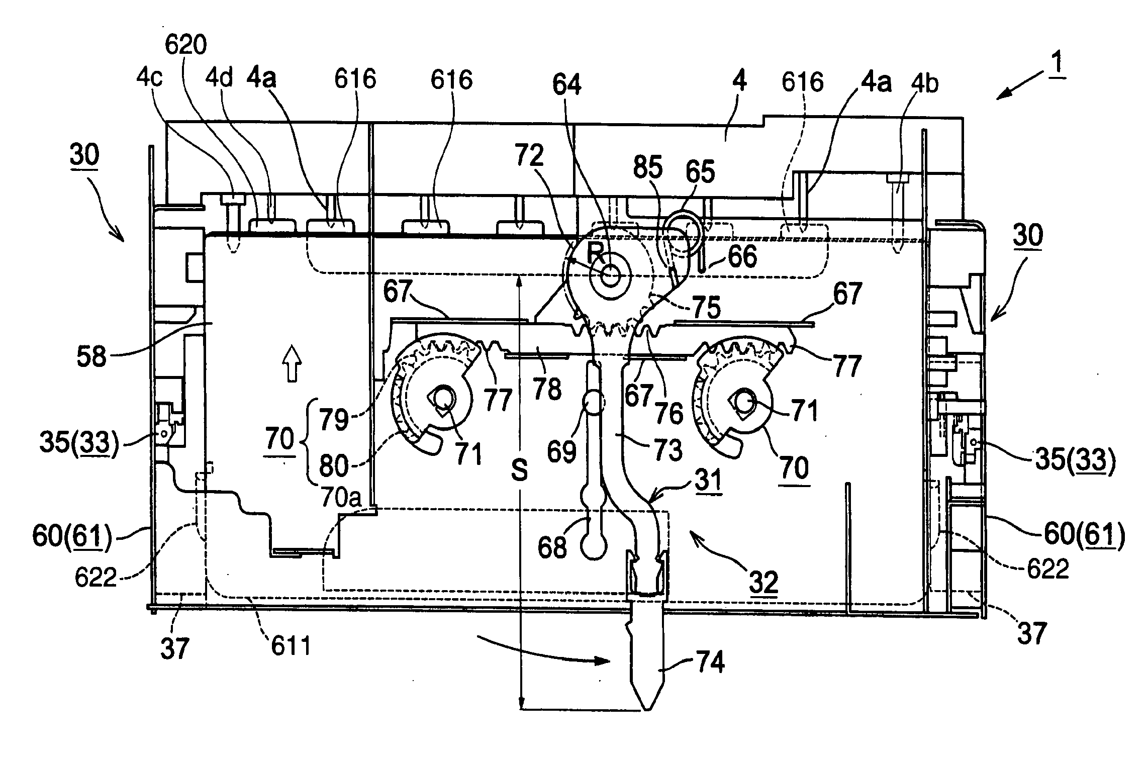
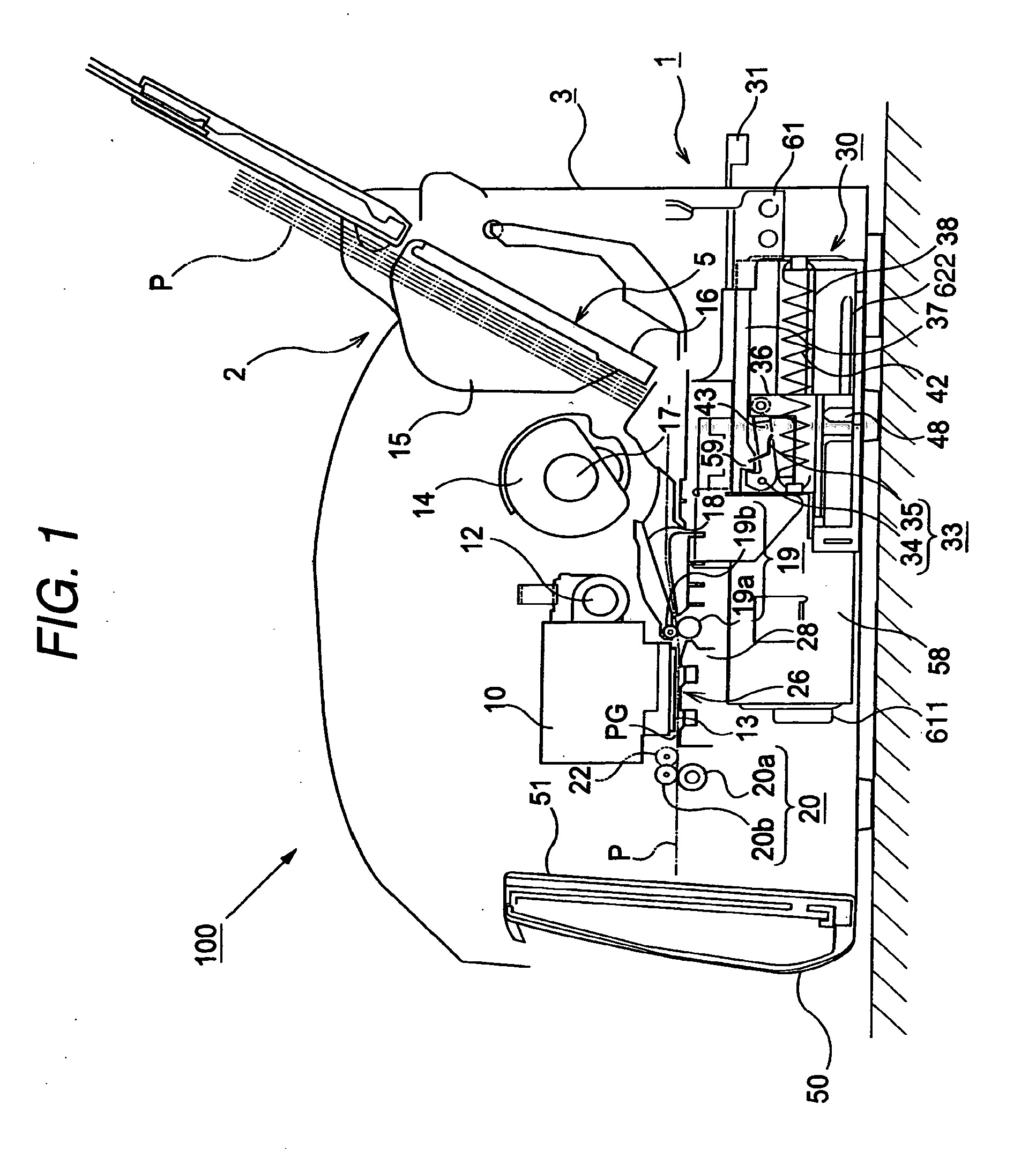
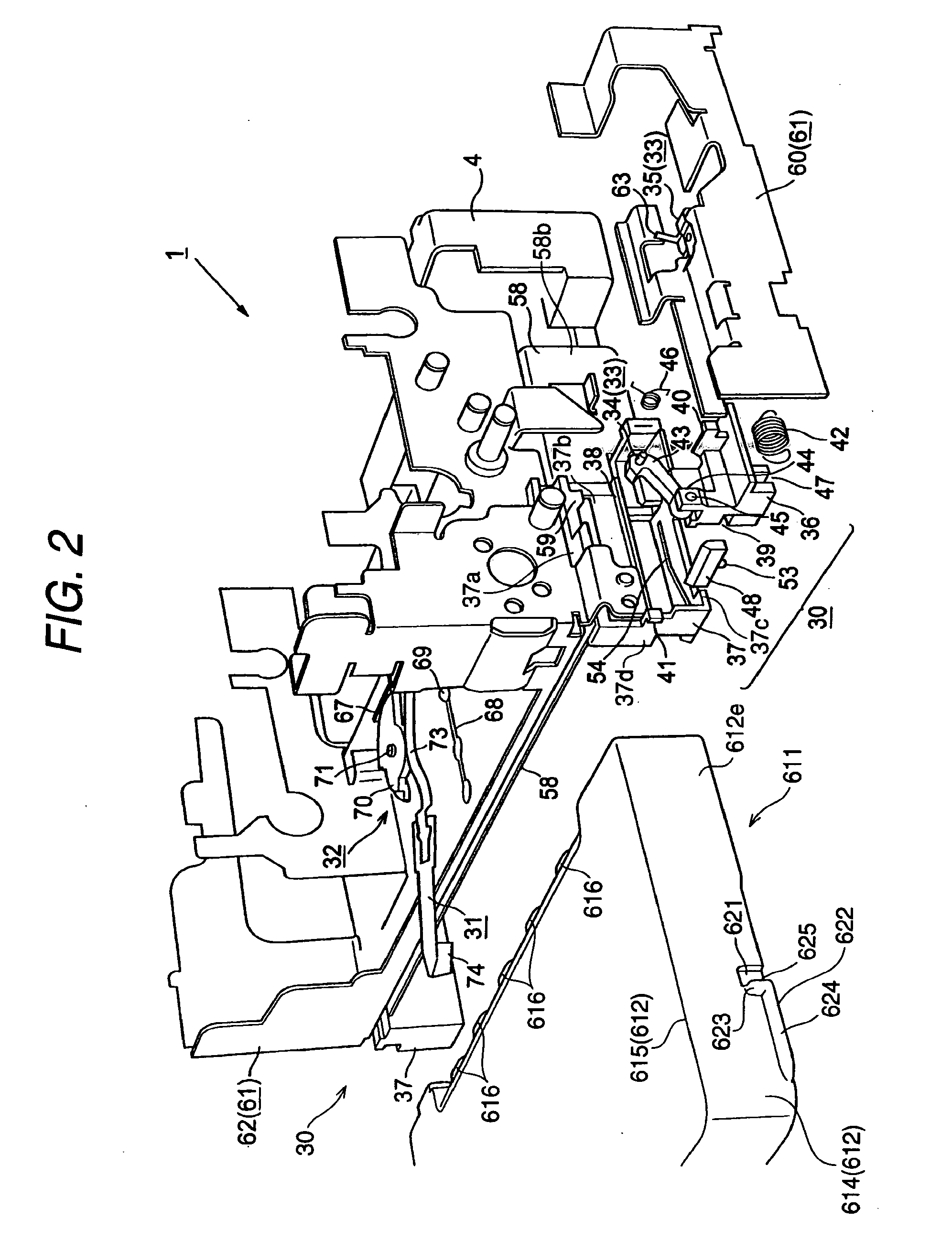
[0226]FIG. 16 is a rear view of an ink jet printer where a lid member is closed. FIG. 17 is a rear view of the ink jet printer where the lid member is open and a lever arm is located at a set position. FIG. 18 is a rear view of an ink jet printer where the lid member is open and the lever arm is located at a reset position. FIG. 19 is an enlarged, oblique perspective bottom view of the periphery of ink cartridge erroneous insertion prevention means. FIGS. 20A, 20B and 20C are bottom views of the operating state of the ink cartridge erroneous insertion prevention means when the ink cartridge is normally inserted. FIGS. 21A and 21B are bottom views of the operating state of the ink cartridge erroneous insertion prevention means when the ink cartridge is erroneously inserted. FIG. 22 is a bottom view of the operating state of the ink cartridge erroneous insertion prevention means when the ink cartridge is inserted while only a cartridge holding means on one si...

second modification

[0233](Second Modification)

[0234]FIG. 23 is a perspective view of an ink cartridge erroneous insertion prevention unit including a collision avoiding unit. FIGS. 24A, 24B and 24C are side cross-sectional views of the operating state of the ink cartridge erroneous insertion prevention unit wherein an ink cartridge is erroneously inserted while a lever arm is located at a position other than a reset position. FIGS. 25A, 25B and 25C are side cross-sectional views of the operating state of the ink cartridge erroneous insertion prevention unit wherein an ink cartridge is inserted while the lever arm is located at the reset position. FIGS. 26A, 26B and 26C are side cross-sectional views of the operating state of an ink cartridge erroneous insertion prevention unit that does not include a collision avoiding unit, wherein an ink cartridge is erroneously inserted while the lever arm is located at a position other than the reset position. FIGS. 27A, 27B and 27C are side cross-sectional views ...

third modification

[0240](Third Modification)

[0241]FIG. 28 is a perspective view of an ink cartridge erroneous insertion unit when a lever arm is located at a position other than the reset position. FIG. 29 is a perspective view of the ink cartridge erroneous insertion prevention unit when the lever arm is located at the reset position. FIG. 30 is an exploded perspective view of the ink cartridge erroneous insertion prevention unit. FIG. 31 is a rear view of the ink cartridge erroneous insertion prevention unit when the lever arm is located at a position other than the reset position. FIG. 32A is a plan view of the ink cartridge erroneous insertion prevention unit in the state wherein the lever arm is located at a position other than the reset position, and FIG. 32B is a plan view of the ink cartridge erroneous insertion prevention unit in the state wherein the lever arm is located at the reset position. FIGS. 33A and 33B are oblique perspective bottom view of the ink cartridge erroneous insertion pre...


PUM


Abstract

A liquid container for a liquid ejection apparatus includes: a case having a liquid containing portion in its interior; a supply portion which is formed on a first side wall of the case, and through which a liquid in the liquid containing portion can flow to an exterior; a contact portion, which can contact a part of a slider of the liquid ejection apparatus to move the slider in a direction in which the liquid container is inserted; and an engagement portion, which is configured to engage a lock portion of the slider. The contact portion and the engagement portion are formed on a second side wall of the case, the second side wall intersecting the first side wall.

Description

CROSS-REFERENCE TO RELATED APPLICATION[0001]This application is a continuation of copending application Ser. No. 11 / 019,510, filed Dec. 21, 2004.BACKGROUND OF THE INVENTION[0002]The present invention relates to an ink cartridge attachment / detachment device that slides an ink cartridge horizontally to load it into the main body of a recording apparatus, and a recording apparatus comprising this attachment / detachment device. The present invention also relates to a liquid ejection apparatus, such as an ink jet recording apparatus, that discharges (ejects) a liquid, such as ink, from a recording head and records on (attaches the liquid to) recording material (an ejected liquid target material), and a liquid cartridge attachment / detachment device provided for the liquid ejection apparatus. The present invention further relates to a liquid container (liquid cartridge) including an ink cartridge.[0003]In this case, such a liquid ejection apparatus includes not only a recording apparatus, s...

Claims


Application Information

Patent Timeline
Patent Type & Authority Applications(United States)
IPC IPC(8): B41J2/175
CPCB41J2/17513B41J2/1752B41J29/02B41J2/17553B41J2/17523E04D13/0409
Inventor SAKAI, YASUTOSHINADA, SATOSHIOKUNO, TOKUJIROKOBAYASHI, SATOSHIKADOTA, SHUICHI
Owner SEIKO EPSON CORP
Why Eureka
Try Eureka