In-line, high energy fiber chirped pulse amplification system

a high energy fiber and chirped pulse technology, applied in the field of high energy fiber laser pulse source construction, can solve the problems of difficult alignment of bulk stretchers and compressors, difficulty in making such single-mode amplifiers, etc., and achieve the effect of optimizing the spectral output of these amplifiers, accurate control, and high average power

Inactive Publication Date: 2007-08-14
IMRA AMERICA
View PDF32 Cites 59 Cited by
  • Summary
  • Abstract
  • Description
  • Claims
  • Application Information

AI Technical Summary

Benefits of technology

[0030]The present invention relates to the use of nonlinearly chirped fiber gratings as pulse stretchers in ultra-compact high energy chirped pulse amplification systems. By minimizing the group delay ripple of the fiber gratings and matching their dispersion to the dispersion of bulk grating compressors, accurately dispersion matched pulse stretchers and compressors can be constructed. Very large pulse stretching ratios can thus be implemented in compact chirped pulse amplification systems. Even larger stretching ratios are possible when using concatenated fiber Bragg gratings.
[0031]Chirped fiber Bragg gratings can be implemented as pulse stretchers for both solid-state amplifier-based and fiber amplifier-based chirped pulse amplification systems. With regards to fiber chirped pulse amplification, the obtainable pulse energies can be maximized by using polarization maintaining, large-core fiber amplifiers. For ease of alignment, and to help maintain single mode operation, fibers with approximately step-like refractive index profiles and circularly symmetric rare-earth doping profiles are preferred.
[0032]Very high average powers can further be obtained by the implementation of double-clad fiber amplifiers. The spectral output of these amplifiers can be optimized by accurate control of the linear polarization state propagating inside the fiber amplifiers.
[0033]Adaptive control of the group delay variations in fiber Bragg gratings can further be performed to enable the minimization of group-delay ripple-induced pulse distortions due to chirped fiber Bragg grating imperfections. Adaptive control of the chirp in fiber gratings is enabled by controlling the temperature and / or pressure (stress) inside distinct fiber grating sections. Adaptive control of the group delay variations in chirped fiber gratings can further be used to compensate for self-phase modulation in high energy amplifiers.
[0034]The combination of fiber grating pulse stretchers and bulk grating compressors allows the generation of a variety of complex pulse shapes optimized for use in advanced micro-structuring applications.
[0035]Finally, fiber grating pulse stretchers can be designed to counteract spectral gain-narrowing in a chirped pulse amplification system, allowing for the generation of pulses with a bandwidth comparable to the gain bandwidth of the optical amplifiers incorporated in the chirped pulse amplification system.

Problems solved by technology

In another suggestion by Grubb et al., U.S. Pat. No. 5,892,615, the use of bent single-mode amplifier fibers has been suggested; the difficulty in making such single-mode amplifiers has also been a limitation in such high power fiber amplifier systems.
Alternative arrangements resorting to the use of bulk stretchers and compressors (as generally used in the state of the art) are generally much more difficult to align, require a significantly larger amount of space for their operation and are only of limited utility in real industrial applications.
However, to date, the mismatch in the dispersion profile between fiber grating pulse stretchers and bulk grating pulse compressors has limited the compressibility of the pulses, limiting their acceptance in the field of ultrafast optics.

Method used


Image

  • In-line, high energy fiber chirped pulse amplification system
  • In-line, high energy fiber chirped pulse amplification system
  • In-line, high energy fiber chirped pulse amplification system

Examples


working example 1

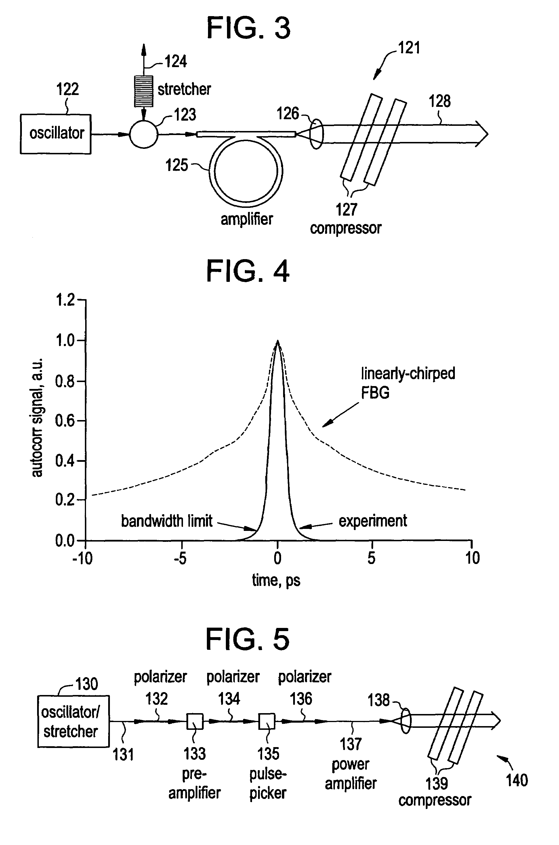
[0049]In a system demonstration, pulses with a full width half maximum (FWHM) width of 350 fs from a passively modelocked Er fiber oscillator operating at a repetition rate of 50 MHz were stretched in a 10 cm long nonlinearly chirped fiber Bragg grating to a width of 700 ps. The nonlinearly chirped fiber grating was designed (e.g., by the iterative method) to provide the same dispersion as the bulk grating compressor; the bulk grating here having a groove spacing of 1200 lines / mm and operated at the Littrow angle. The maximum group delay variations (or group delay ripple) from the designed group delay in the chirped fiber Bragg grating were measured at ±<2 ps. The oscillator pulse energy was 100 pJ. After amplification by a factor of 10, the pulses were recompressed in the bulk grating compressor. The recompressed pulses had a FWHM width of ≈700 fs sitting on an additional pedestal with a FWHM width of 3 ps, containing about 2% of the pulse energy. Hence a compression ratio of up to...


PUM


Abstract

By writing non-linear chirp into fiber Bragg gratings, greater control over dispersion compensation in CPA systems is obtained, such that, for example, the dispersion profile of the fiber Bragg grating and a bulk compressor may be matched. An iterative method of writing the fiber grating can reduce the group delay ripple to very low levels; and adaptive control of the fiber grating dispersion profile can further reduce these levels, while in addition offering greater acceptable yield in the manufacture of such gratings. Fiber Bragg gratings may be designed so as to provide customized pulse shapes optimized for various end uses, such as micromachining, for example, and may also be used to counteract gain-narrowing in a downstream amplifier.

Description

CROSS REFERENCE TO RELATED APPLICATIONS [0001]This application claims benefit of Provisional Application No. 60 / 474,999, filed Jun. 3, 2003; the disclosure of which is incorporated by reference.FIELD OF THE INVENTION [0002]This invention relates to the construction of compact high energy fiber laser pulse sources, methods of designing and using such sources, and adaptive control techniques therefor.BACKGROUND OF THE INVENTION [0003]Over the last several years, fiber lasers and amplifiers have been regarded as the most promising candidates for pulse sources for industrial applications, due to their unique simplicity of construction. Large core fiber amplifiers and specifically large core diffraction limited multi-mode amplifiers (as described by M. E. Fermann and D. Harter, ‘Single-Mode Amplifiers and Compressors based on Multi-Mode Optical Fibers’, U.S. Pat. No. 5,818,630) enable the amplification of optical signals to levels where micro-machining and laser marking become possible. ...

Claims


Application Information

Patent Timeline
Patent Type & Authority Patents(United States)
IPC IPC(8): G02B6/02G02B6/26H01SH01S3/00H01S3/067H01S3/23
CPCH01S3/0057H01S3/06754H01S3/06712H01S3/06725H01S3/0092H01S3/10015H01S3/005H01S3/0085H01S3/094007
Inventor FERMANN, MARTIN E.IMESHEV, GENNADYHARTL, INGMARHARTER, DONALD J.
Owner IMRA AMERICA
Why Eureka
Try Eureka