Variable Tomographic Scanning with Wavelength Scanning Digital Interface Holography

a technology of tomographic scanning and digital interface, applied in the field of holography, can solve the problems of inability to make his invention practical, time-consuming and cumbersome conventional process of holography using photographic plates, and inability to realize real-time process

Active Publication Date: 2008-06-12
UNIV OF SOUTH FLORIDA
View PDF8 Cites 81 Cited by
  • Summary
  • Abstract
  • Description
  • Claims
  • Application Information

AI Technical Summary

Problems solved by technology

At the time, however, his invention could not be made practical because there were no light sources available with the required coherence.
The conventional process of holography using photographic plates, however, is time-consuming and cumbersome.
Real time process is not feasible unless photorefractives and other nonlinear optical m...

Method used


Image

  • Variable Tomographic Scanning with Wavelength Scanning Digital Interface Holography
  • Variable Tomographic Scanning with Wavelength Scanning Digital Interface Holography
  • Variable Tomographic Scanning with Wavelength Scanning Digital Interface Holography

Examples


Embodiment Construction

[0160]Digital Holography for Biological Microscopy

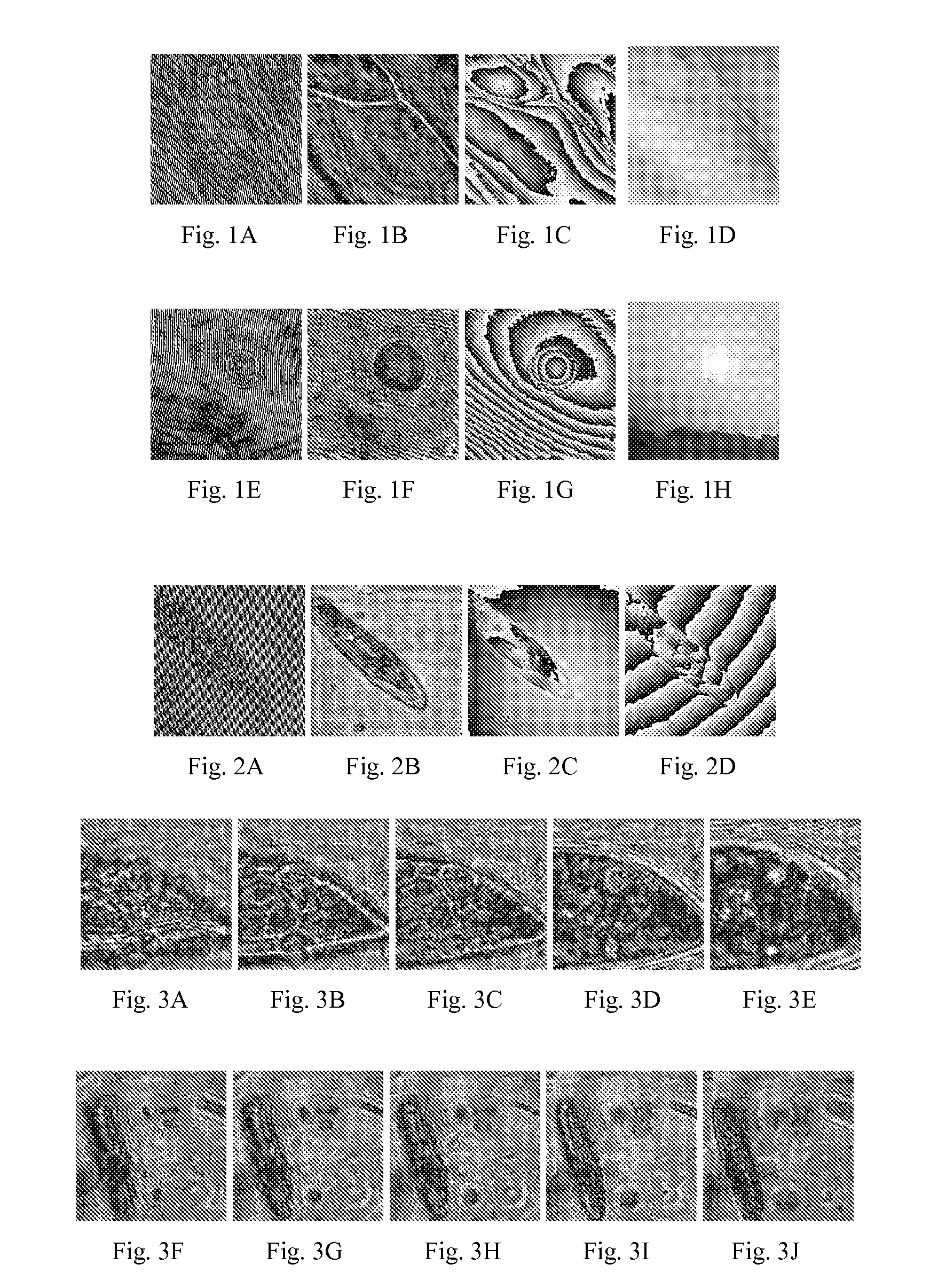
[0161]Examples of digital holography of onion cells are shown in FIGS. 1A-D and 1E-H. FIGS. 1A-D depict a 100×100 μm2 area (416×416 pixels) of a layer of onion cells with z=174 μm. The cell walls are sharply focused in the amplitude image and the phase image shows accurate representation of optical thickness, modulo wavelength, of the cell bodies. The images of 70×70 μm2 area (464×464 pixels) in FIGS. 1E-H focus on a nucleus of a cell with z=62 μm. The phase image is a clear view of the optical thickness variation of the nucleus in the middle of the bulged body of the cell. A simple quantitative analysis of the cell's index of refraction is possible. By counting the number of fringes, the optical thickness of the nucleus is easily determined to be 3.5λ=1.86 μm thicker than the cell body. Assuming that the shape of the nucleus is spherical so that its thickness is the same as the 19 μm diameter of the circular image, then the refracti...


PUM


Abstract

A series of holograms is recorded by synchronizing a camera with laser pulses under the control of a digital delay generator. Amplitude and phase images are calculated while image distances are adjusted for the best focus on the object under observation. The amplitude and phase images are reconstructed while adjusting the image distances over a predetermined range to maintain the object in focus. Numerical superposition of a plurality of holographic fields taken with varying wavelengths provides high resolution microscopic three-dimensional imaging. Numerical reconstruction is based on an angular spectrum method that enables calculation of the image at any distance from the hologram plane. Wavelength scanning digital interference holography also enables image reconstruction along an arbitrarily tilted plane.

Description

CROSS-REFERENCE TO RELATED APPLICATIONS[0001]This application is a continuation of prior filed International Application, Serial Number PCT / US06 / 25610 filed Jun. 29, 2006, which claims priority to U.S. provisional patent application No. 60 / 694,856 filed Jun. 29, 2005 which is hereby incorporated by reference into this disclosure.STATEMENT OF GOVERNMENT INTEREST[0002]This invention was made with U.S. government support under grant No. DBI0243237 awarded by the National Science Foundation. The U.S. government has certain rights in the invention.BACKGROUND OF THE INVENTION[0003]1. Field of the Invention[0004]This invention relates to holography. More particularly, it relates to wavelength scanning digital interference holography.[0005]2. Description of the Prior Art[0006]Dennis Gabor is credited with the invention of holography in 1948 while attempting to improve the resolution of electron microscopy. At the time, however, his invention could not be made practical because there were no...

Claims


Application Information

Patent Timeline
IPC IPC(8): G06K9/00
CPCG01B9/021G03H1/00G03H1/0866G03H2222/13G03H2001/0445G03H2001/266G03H2001/043G03H2222/33
Inventor KIM, MYUNG K.
Owner UNIV OF SOUTH FLORIDA
Why Eureka
Try Eureka