Optical cross-connect using wavelength selective switches

a wavelength selective switch and optical cross-connect technology, applied in the field of optical cross-connect, can solve the problems of increased product cost, increased number, and above-described architecture of conventional optical cross-connects,

Inactive Publication Date: 2008-06-12
FUJITSU LTD
View PDF2 Cites 24 Cited by
  • Summary
  • Abstract
  • Description
  • Claims
  • Application Information

AI Technical Summary

Benefits of technology

[0038]In view of the foregoing, it is an object of the present invention to provide an optimally-sized optical cross-connect that switches optical signal paths with a minimum number of wavelength selective switches and their interconnections.

Problems solved by technology

The above-described architectures of conventional optical cross-connects may not be optimal in terms of how they use WSSs.
On the other hand, the increased use of WSSs also means increased product cost, as well as an increased number of interconnections between them, thus making a cross-connect device more complex and larger.
Table T63, however, shows many switching patterns marked “YES.” This means that the conventional optical cross-connect 60 is not optimized as to the simultaneity of its switching paths.

Method used


Image

  • Optical cross-connect using wavelength selective switches
  • Optical cross-connect using wavelength selective switches
  • Optical cross-connect using wavelength selective switches

Examples


Embodiment Construction

[0056]Preferred embodiments of the present invention will be described below with reference to the accompanying drawings, wherein like reference numerals refer to like elements throughout.

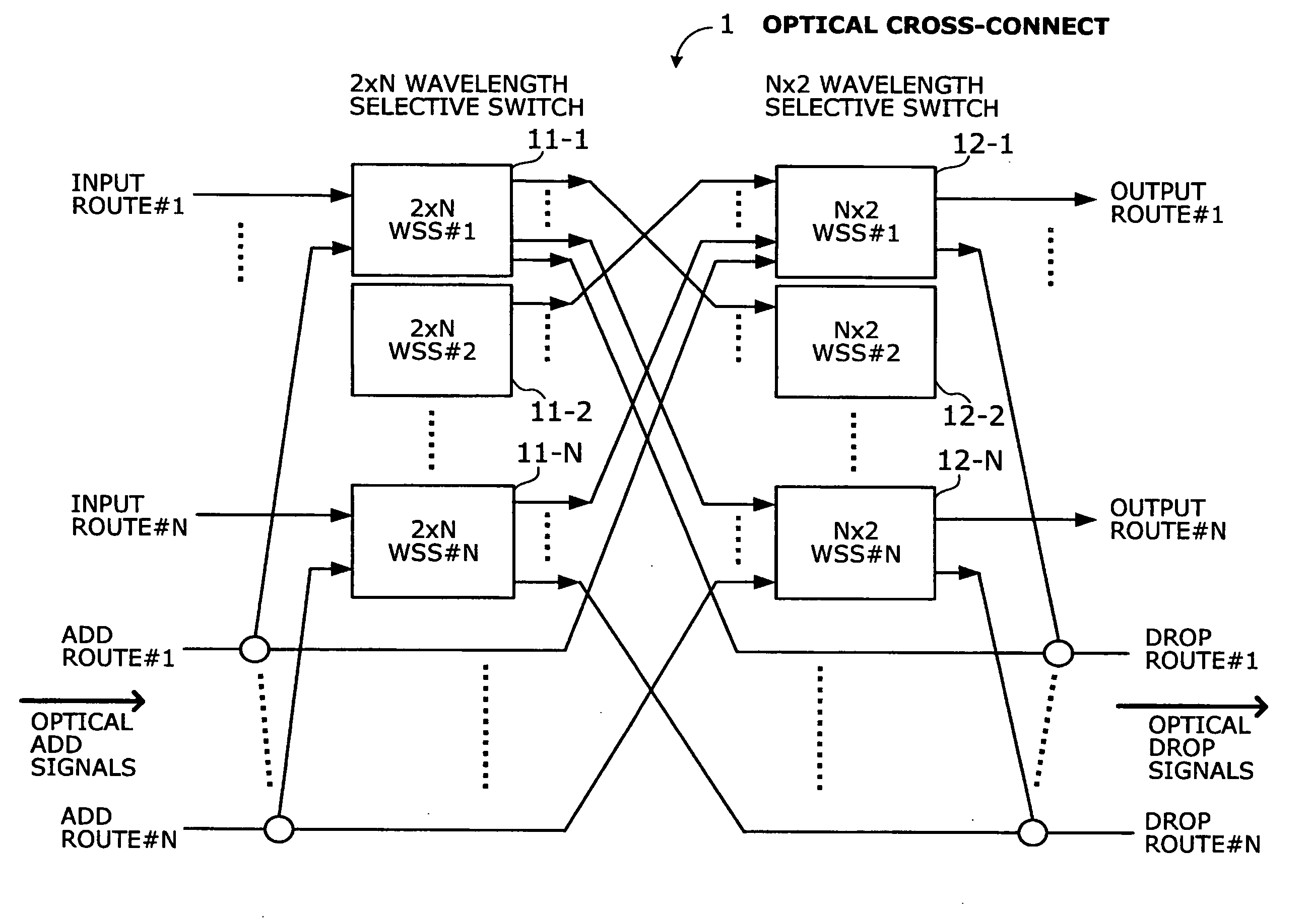
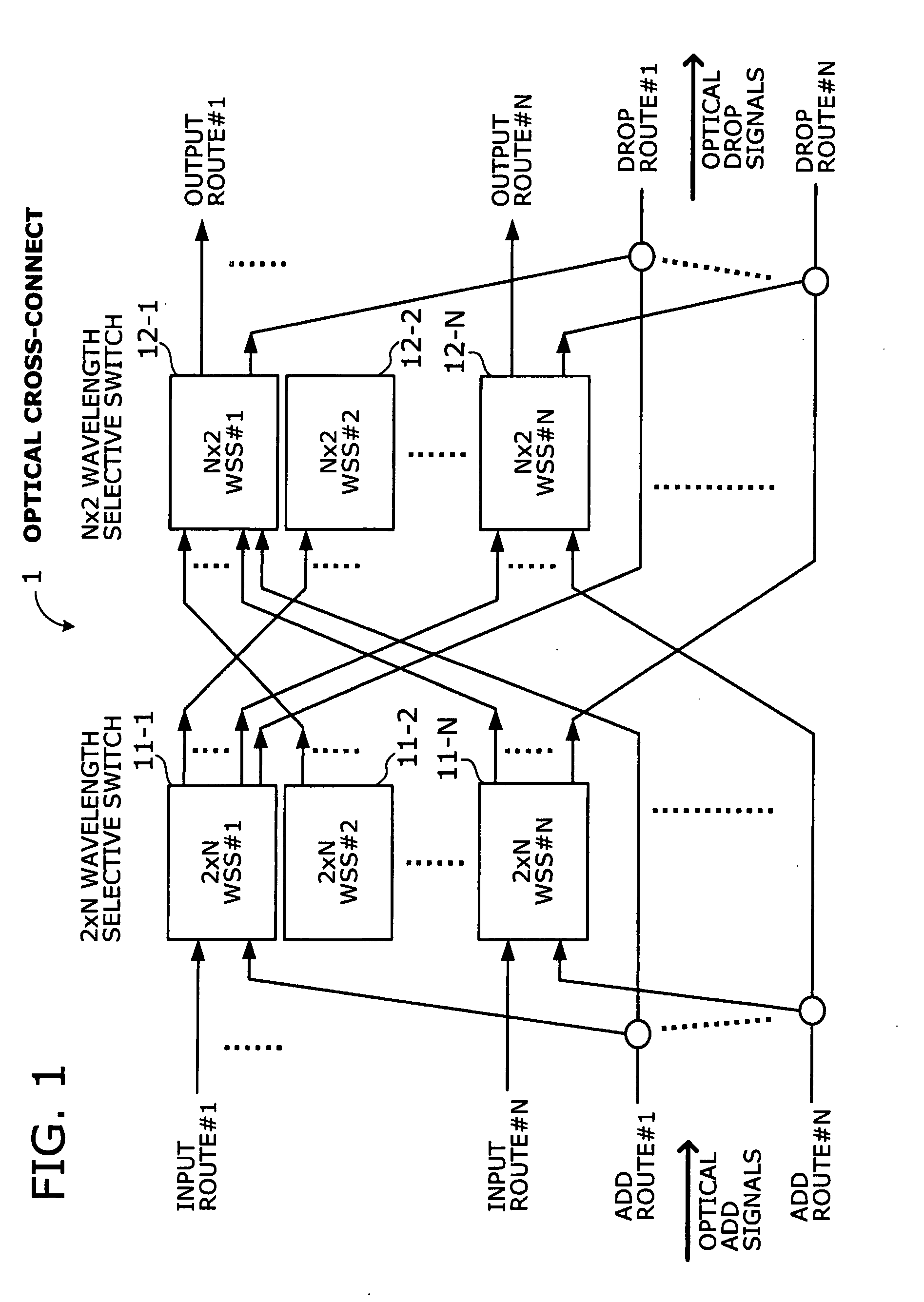
[0057]FIG. 1 is a conceptual view of an optical cross-connect according to the present invention. This optical cross-connect 1 switches optical signals between N routes, which include input routes, N output routes, N add routes, and N drop routes (N=1, 2, . . . ). To perform this function, the optical cross-connect 1 includes (a) 2-input N-output (2×N) wavelength selective switches (WSS) 11-1 to 11-N coupled respectively to N input routes, and (b) N-input 2-output (N×2) wavelength selective switches 12-1 to 12-N coupled respectively to N output routes.

[0058]The nth 2×N wavelength selective switch (shown as 2×N WSS#n in FIG. 1) (n=1, 2, . . . N) coupled to the nth input route (input route #n) receives an optical signal from the nth input route at its first input port and an optical add signal from t...


PUM


Abstract

An optimally-sized optical cross-connect that switches optical signal paths with a minimum number of wavelength selective switches and their interconnections. To switch optical signals of N routes (N=1, 2, . . . ), an optical cross-connect includes a 2×N (2-input, N-output) wavelength selective switch for each of N input routes and a N×2 (N-input, 2-output) wavelength selective switch for each of N output routes. One input port of each 2×N wavelength selective switch receives an optical signal from a corresponding input route, while the other input port of the same receives an optical add signal from a corresponding add route. One output port of each N×2 wavelength selective switch outputs an optical signal to a corresponding output route, while the other output port outputs an optical drop signal to a corresponding drop route.

Description

CROSS-REFERENCE TO RELATED APPLICATIONS[0001]This application is based upon and claims the benefits of priority from the prior Japanese Patent Application No. 2006-330120 filed Dec. 7, 2006, the entire contents of which are incorporated herein by reference.BACKGROUND OF THE INVENTION[0002]1. Field of the Invention[0003]The present invention relates to an optical cross-connect, and more particularly to an optical cross-connect that switches optical signals of N routes (N=1, 2, . . . ).[0004]2. Description of the Related Art[0005]Many optical network systems use the wavelength-division multiplexing (WDM) technology to interconnect network nodes such as cities and countries. WDM transmission systems involve various control techniques to, for example, deliver optical signals with different wavelengths to intended destinations, or to add or drop a desired wavelength to / from a desired route of optical signals. The latter is known as “optical add and drop multiplexing” (OADM). Also require...

Claims


Application Information

Patent Timeline
Patent Type & Authority Applications(United States)
IPC IPC(8): H04J14/00H04B10/27G02B26/08H04B10/291H04J14/02H04Q3/52
CPCG02B6/3512G02B6/3542G02B6/356H04J14/0209H04J14/0212H04Q2011/0052H04J14/0217H04Q11/0005H04Q2011/0015H04Q2011/0016H04Q2011/003H04J14/0213
Inventor AKIYAMA, YUICHITERAHARA, TAKAFUMIOOI, HIROKI
Owner FUJITSU LTD
Why Eureka
Try Eureka