

Relay connector
- Summary
- Abstract
- Description
- Claims
- Application Information
AI Technical Summary
Benefits of technology
Problems solved by technology
Method used
Image

Examples
first embodiment
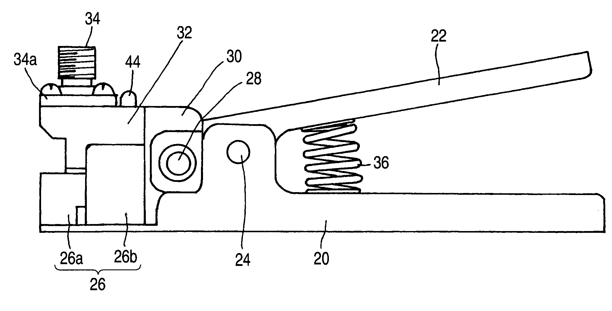
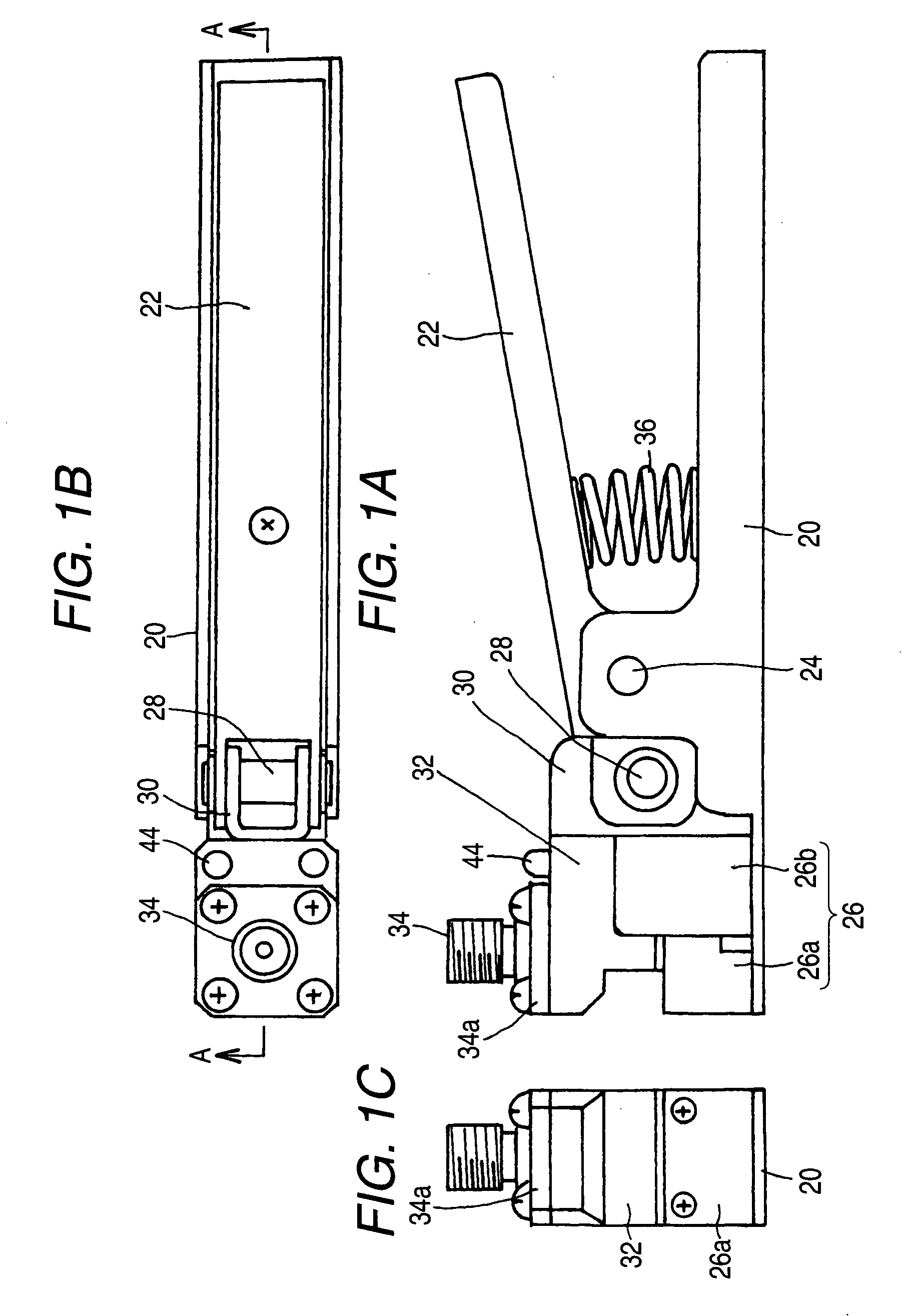
[0042]Now, the invention will be described referring to FIGS. 1A to 7. In FIGS. 1A to 7, the same or equivalent members as in FIGS. 9 and 10 will be denoted with the same reference numerals and overlapping descriptions will be omitted.
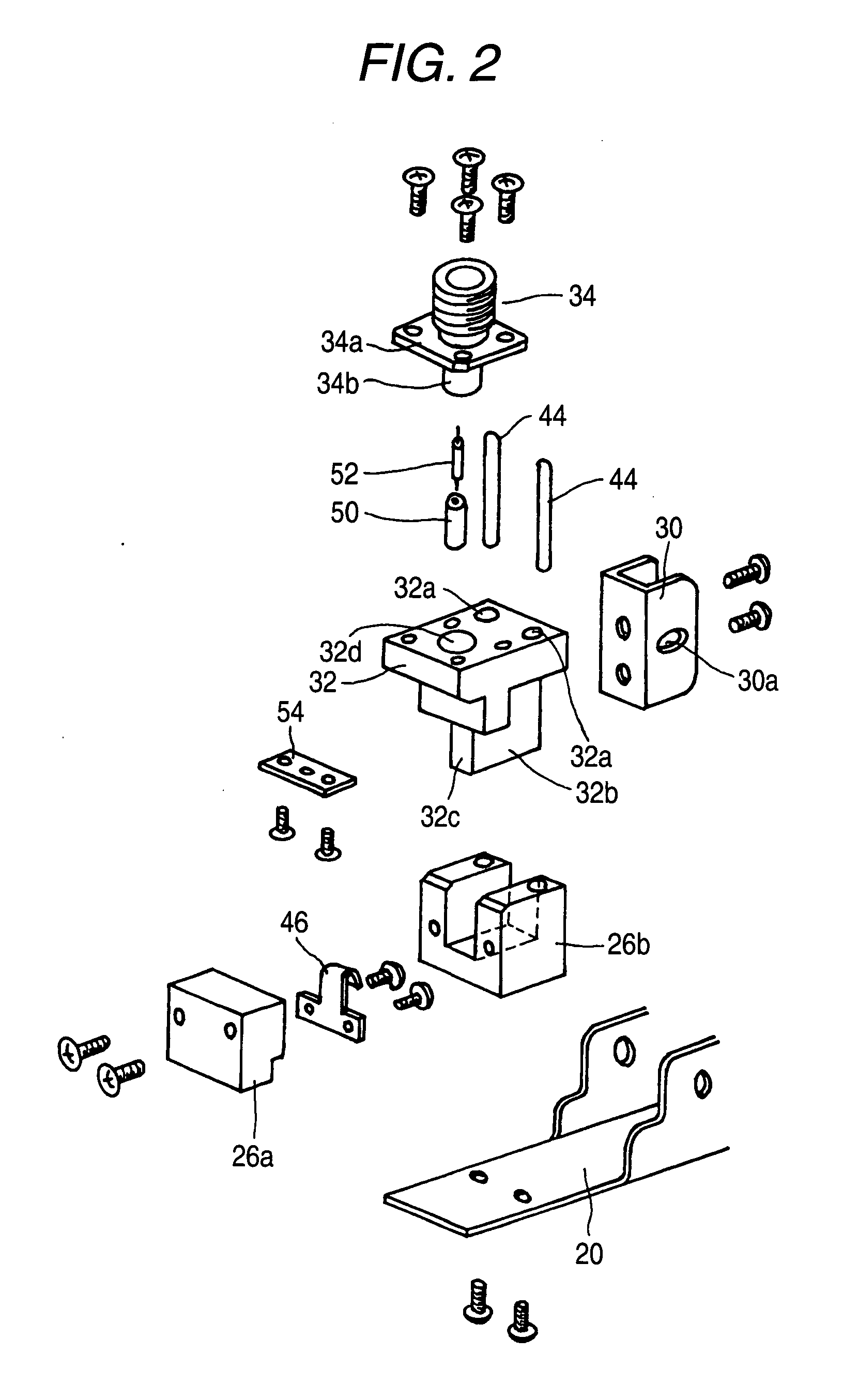
[0043]In FIGS. 1A to 7, in the relay connector in the first embodiment of the invention, a second operating lever 22 is mounted on a first operating lever 20 by means of a swing shaft 24 so as to swing. A board GND block 26 formed of electrically conductive material is fixed to an end of the first operating lever 20 at one side with respect to the swing shaft 24, with screws. This board GND block 26 includes aboard receiving part 26a and a movement holding part 26b which are fixed to each other with screws. Moreover, a connecting member 30 is connected to an end of the second operating lever 22 at one side with respect to the swing shaft 24, by means of a second swing shaft 28 which is in parallel with the swing shaft 24. An outer shell GND block 32 fo...
second embodiment
[0048]Now, the invention will be described referring to FIG. 8. In FIG. 8, the same or equivalent members as in FIGS. 1A to 7 will be denoted with the same reference numerals and overlapped descriptions will be omitted.
[0049]In the relay connector in the second embodiment of the invention, a dielectric member covering a core conductor 64c of a coaxial connector 64 is not projected from an outer shell GND 64a, but only the core conductor 64c exposed by peeling from the dielectric member is projected. Therefore, an insulating pipe 60 is inserted into the through hole 32d in the outer shell GND block 32 along an entire length of the through hole 32d, and the core conductor 64c projected from the outer shell GND 64a is inserted into one end of the insulating pipe 60. A plunger at one end of the probe 52 which is inserted into the insulating pipe 60 is so adapted as to be resiliently contacted with a distal end face of the core conductor 64c, inside the insulating pipe 60. An inner diame...
PUM
 Abstract
Description
Claims
Application Information