Method for pointing high-gain antennas to reduce interference in mobile networks

a high-gain antenna and mobile network technology, applied in the field of communication systems, can solve the problems of not being able to adapt to dynamic systems, requiring and consuming bandwidth, and slow response to the dynamics of highly mobile transmitters and receivers, so as to reduce interference and minimize interference

Active Publication Date: 2008-06-12
THE BOEING CO
View PDF9 Cites 26 Cited by
  • Summary
  • Abstract
  • Description
  • Claims
  • Application Information

AI Technical Summary

Benefits of technology

[0011]In another aspect of the disclosure, a method for selecting a direction to point at least one antenna to reduce interference, comprising: loading a computer with an antenna pattern for a node receiving identity of at least one primary node; continually receiving data about azimuth and elevation of each primary and secondary node and computing antenna direction to minimize interference.

Problems solved by technology

This approach is too slow to respond to the dynamics of highly mobile transmitters and receivers.
Unfortunately, this approach requires and consumes bandwidth that could otherwise be devoted to carrying data.
Furthermore, this approach is not suitable for dynamic systems that often communicate at low elevation angles where multi-path interference causes rapid changes in signal intensity.
However, this approach is not suitable for dynamic systems wherein communication nodes often move across the sky faster than a large antenna can steer.
Furthermore, larger antennas cost more to purchase, install, and maintain, and are less suitable for use with a mobile node.

Method used


Image

  • Method for pointing high-gain antennas to reduce interference in mobile networks
  • Method for pointing high-gain antennas to reduce interference in mobile networks
  • Method for pointing high-gain antennas to reduce interference in mobile networks

Examples


Embodiment Construction

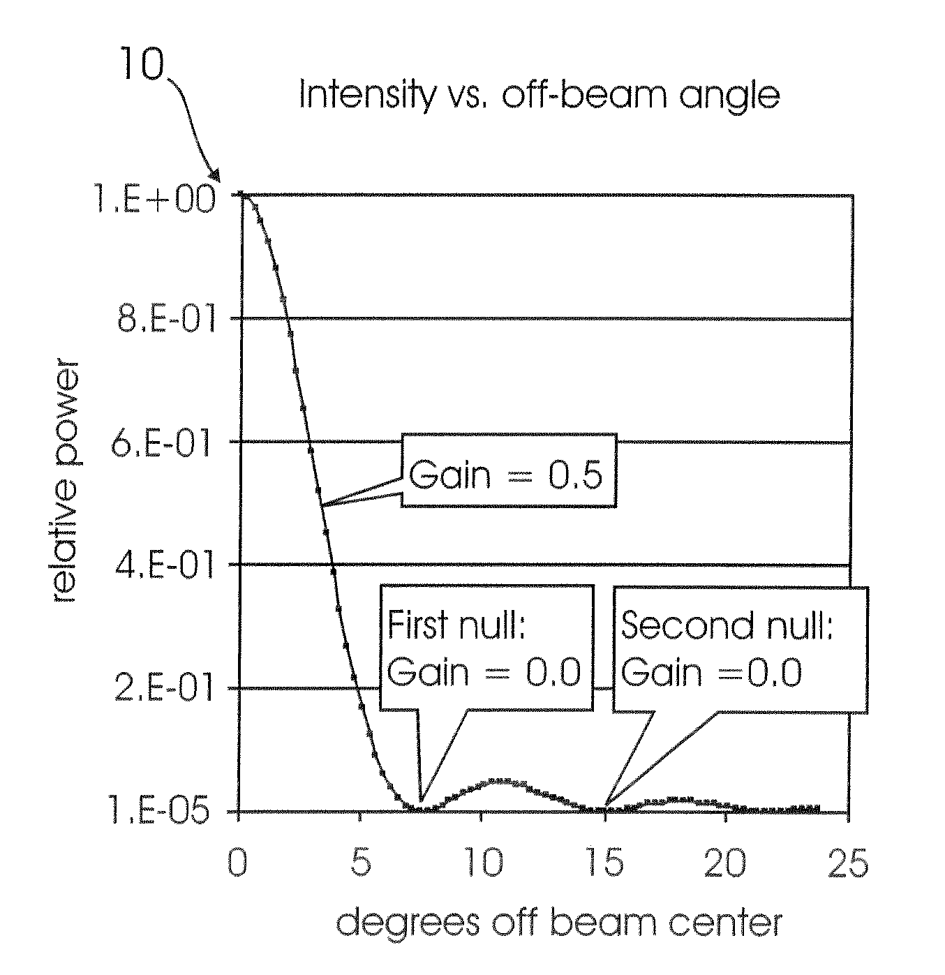
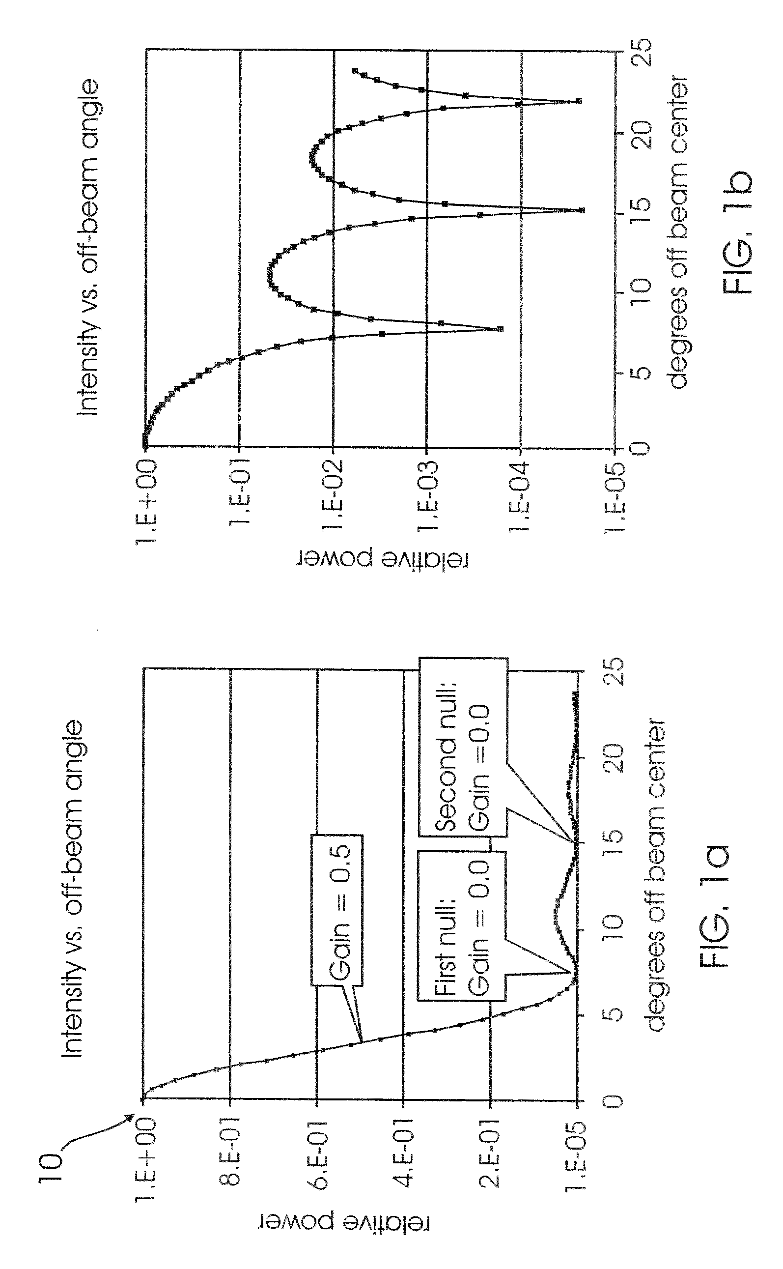
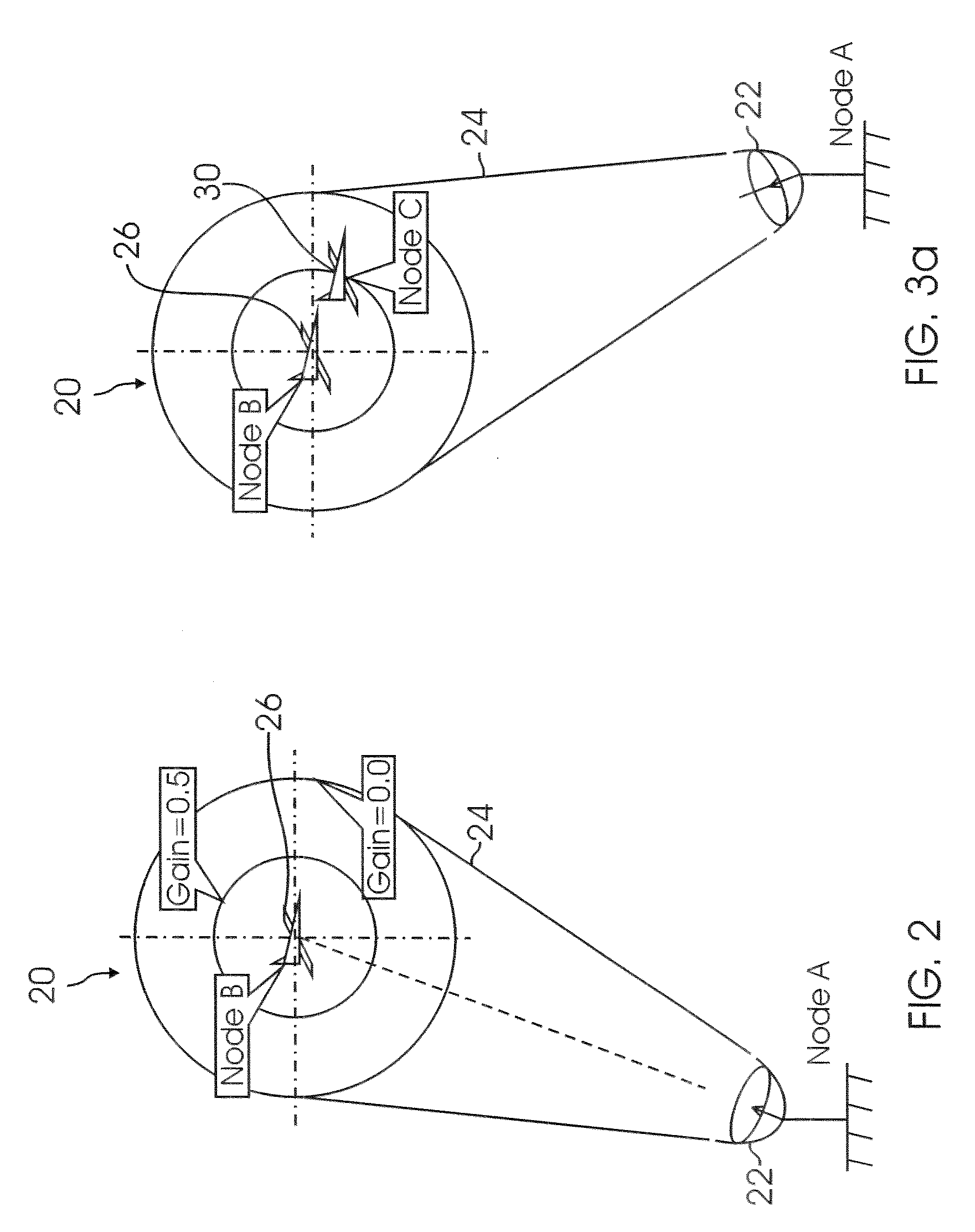
[0030]As used herein, the designations “node A” and “node B” refer to nodes in the process of establishing a link, for example, an antenna (node A) to an aircraft (node B). The designations “node C” and “node D” refer to two nodes other than nodes A and B in communication with a node designated “node E”, and are capable of linking with node E, but not necessarily with node A or with node B. From the standpoint of node A and node B in a network, there may be zero, one, or a plurality of nodes C, nodes D, and nodes E. In addition, there may be zero, one, or a plurality of nodes E for any particular node C or node D, as any particular node C or node D may be in communication with zero, on e. or more other nodes.

[0031]A mobile network includes a plurality of nodes at which a high-grain antenna may be pointed, such as target nodes, and at least one stationary node. Target nodes include, but are not limited to aircraft, spacecraft, a satellite in geostationary orbit or a surface vehicle; ...


PUM


Abstract

A method for reducing interference in a mobile network is provided. The method includes determining locations of a plurality of nodes in the mobile network; steering at least one antenna at a node in the plurality of nodes in the mobile network; estimating intensity of signals from the at least one antenna at each of the plurality of nodes; determining optimal direction to steer the at least one antenna to reduce interference; and steering the at least one antenna in the optimal direction.

Description

BACKGROUND[0001]1. Field of Disclosure[0002]The disclosure generally relates to communication systems and, more particularly, to a method for reducing interference in mobile networks.[0003]2. Related Art[0004]For many communication applications, high gain antennas are used to improve performance. For example, high gain antennas are used to improve the performance of microwave links used for commercial telephony and satellite links. In most applications, the antenna beam points to a single communication node, such as a satellite or an aircraft. Different antenna beams may use the same frequency as long as the antenna beams do not overlap spatially.[0005]However, situations may exist while a high-grain antenna at node A may be used to communicate with a communication node B, while one or more other communication nodes, C and perhaps D, are within the beam width of the high-gain antenna signals sent from communication node A to communication node B, in this case, the signals being sent...

Claims


Application Information

Patent Timeline
Patent Type & Authority Applications(United States)
IPC IPC(8): H04B1/00
CPCH01Q1/246H04W16/28H01Q3/2605H01Q3/08
Inventor TILLOTSON, BRIAN J.
Owner THE BOEING CO
Why Eureka
Try Eureka