Eccentric Oscillating-Typr Planetary Gear Device

Active Publication Date: 2008-06-12
NABLESCO CORP
View PDF5 Cites 18 Cited by
  • Summary
  • Abstract
  • Description
  • Claims
  • Application Information

AI Technical Summary

Benefits of technology

[0030]As described above, if the amount H of eccentricity is not less than 0.5 times the radius R, the tooth tops of the external teeth interfere with the inner periphery of the internally toothed gear. However, since the external teeth are cut by a predetermined amount from the tooth tops, the interference of the internal teeth and the inner periphery of the internally toothed gear is prevented. Meanwhile, according to a tenth aspect of the invention, since the inner periphery of the internally toothed gear between adjacent internal teeth is cut by a predetermined depth, the interference of the external teeth and the inner periphery of the internally toothed gear is prevented. Moreover, if t

Problems solved by technology

As a result, as described above, the movement of the meeting point radially

Method used


Image

  • Eccentric Oscillating-Typr Planetary Gear Device
  • Eccentric Oscillating-Typr Planetary Gear Device
  • Eccentric Oscillating-Typr Planetary Gear Device

Examples


Example

[0058]A first embodiment of the invention will now be described with reference to the drawings.

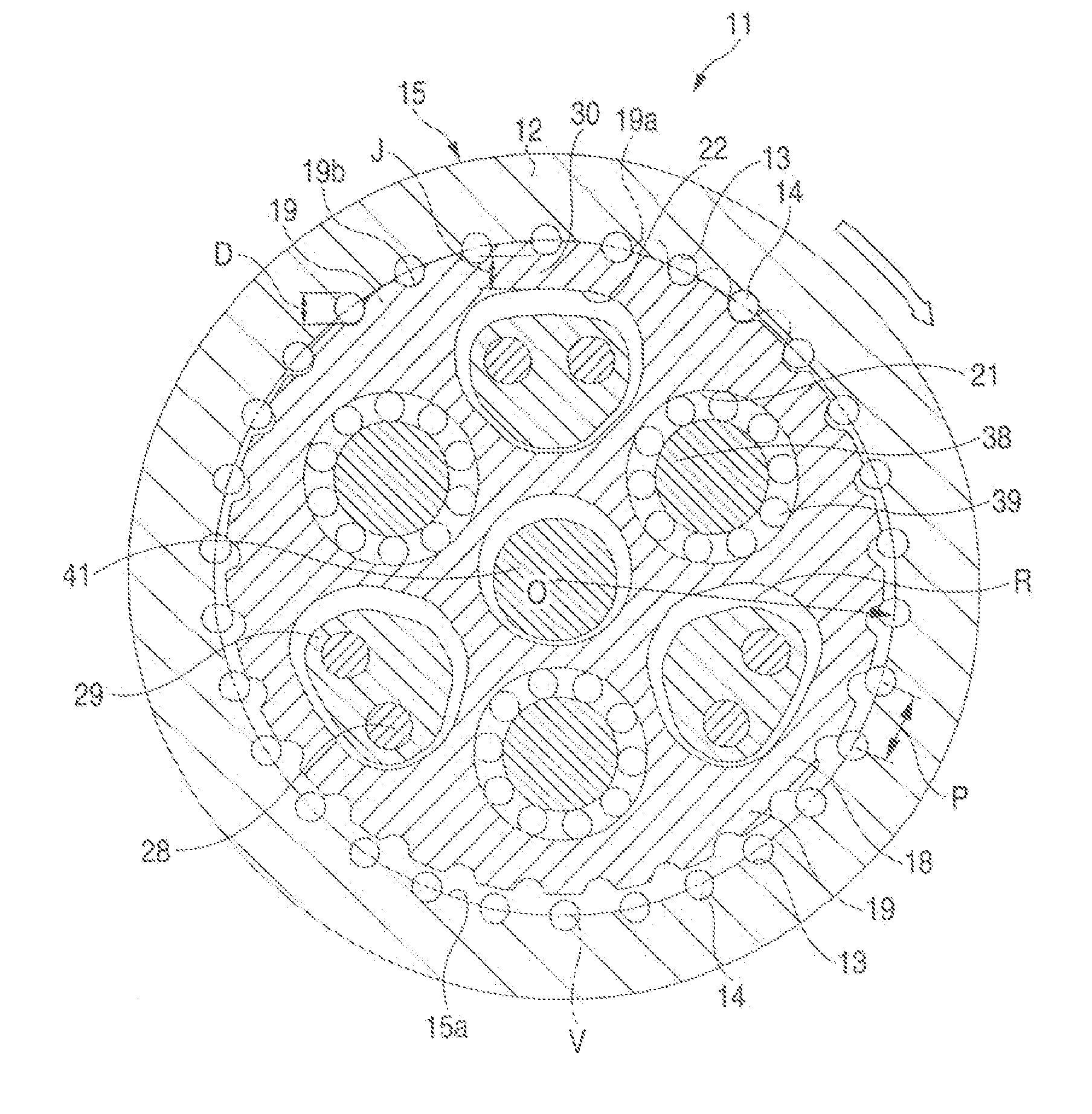
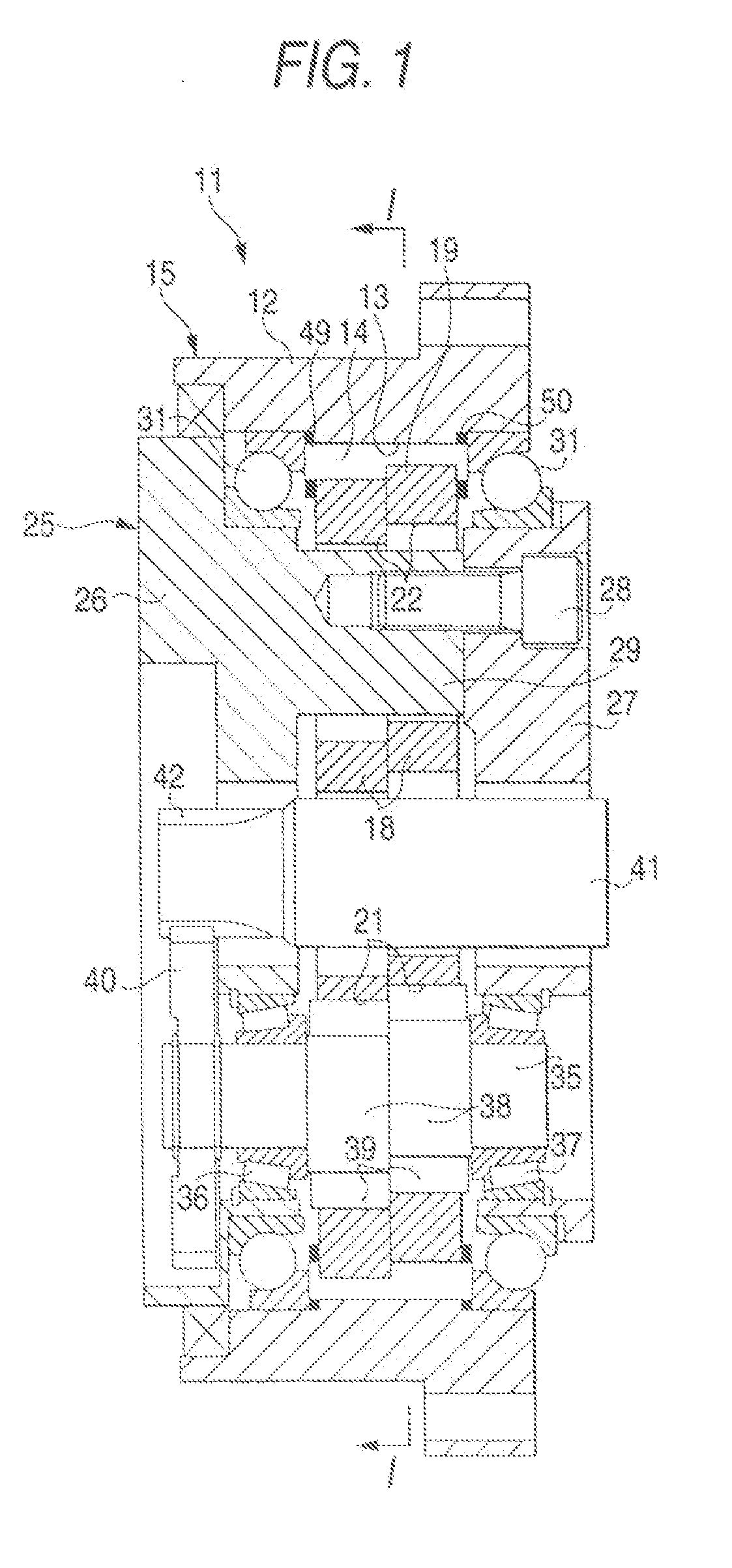
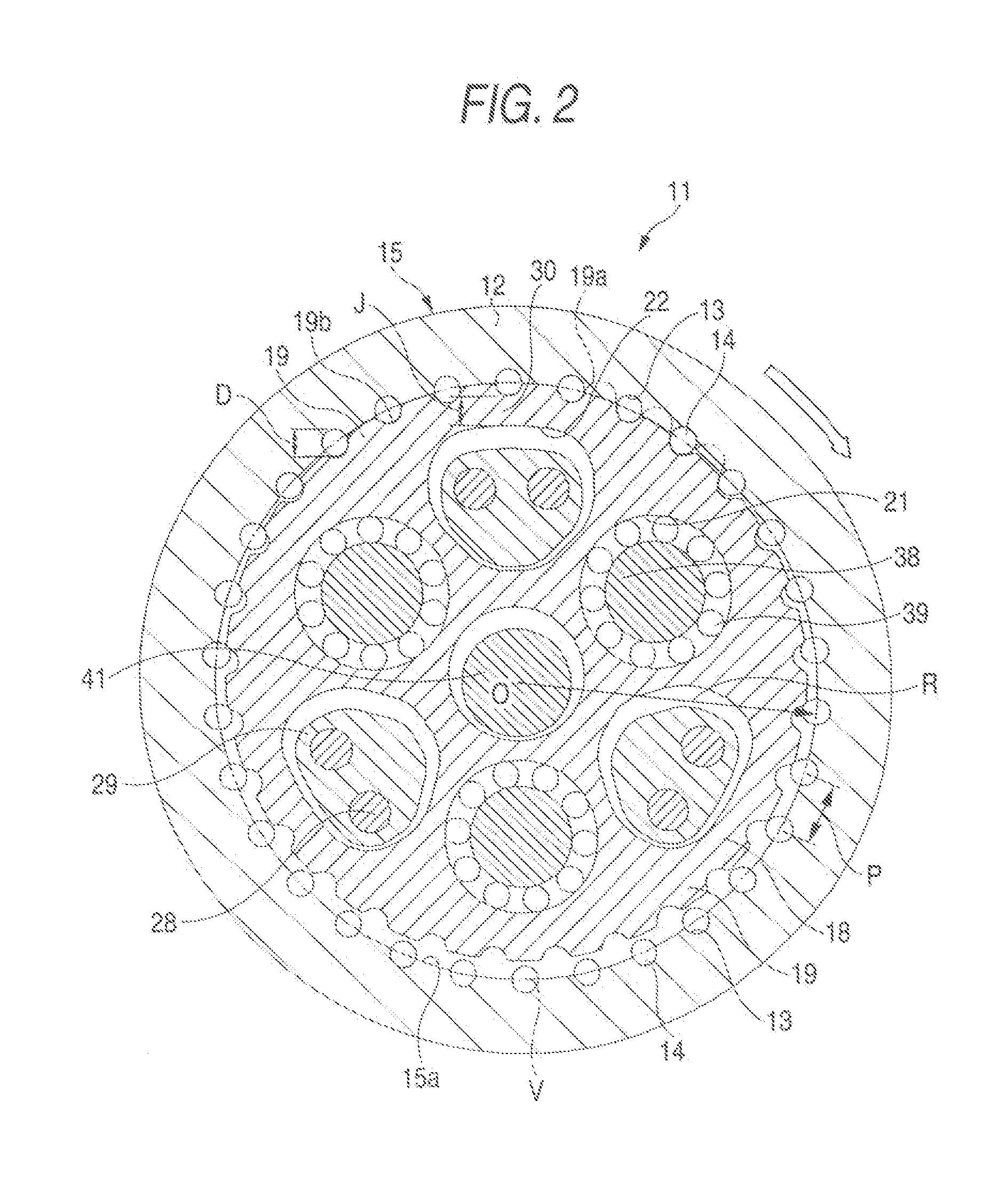
[0059]In FIGS. 1 and 2, reference numeral 11 denotes an eccentric oscillating-type planetary gear device. The planetary gear device 11 has an approximately cylindrical rotary case 12 that is mounted on an arm or hand of a robot (not shown). A plurality of pin grooves 13 having semicircle sectional shapes are formed at a central portion in an axial direction at an inner periphery of the rotary case 12. The pin grooves 13 extend in the axial direction and are arranged at constant distances in a circumferential direction. Herein, the pin grooves 13 are disposed at constant pitches P. Reference numeral 14 denotes internal teeth having a plurality of pillar pins (equal in number to the pin grooves 13). The internal teeth (pins) 14 are provided at constant distances (constant pitches P) on the inner periphery of the rotary case 12 in the circumferential direction, such that approximately halves ...

Example

Second Embodiment

[0091]FIGS. 7 and 8 are diagrams showing a second embodiment of the invention. In the second embodiment, unlike the first embodiment, cutting of the external teeth 19 is not performed, but the inner periphery of the internally toothed gear 15 (the rotary case 12) between adjacent internal teeth (pins) 14 and the inner periphery in the vicinity of the internal teeth (pins) 14 are cut by a depth equal to or more than an amount of the external teeth 19 exceeding the inner periphery, for example, in this embodiment, by a depth equal to approximately half of the diameter D of the internal teeth (pins) 14, such that the interference of the external teeth 19 and the inner periphery 15a of the internally toothed gear 15 (the rotary case 12) after cutting is prevented.

[0092]As a result, radially outer ends of the internal teeth (pins) 14 come into linear contact with the inner periphery 15a of the internally toothed gear 15 after cutting, and thus radial components of the dr...

Example

Third Embodiment

[0095]Hereinafter, a third embodiment of the invention will be described with reference to the drawings.

[0096]In FIGS. 9, 10, and 11, reference numeral 111 denotes an eccentric oscillating-type planetary gear device that is used in a robot or the like. The planetary gear device 111 has an approximately cylindrical rotary case 112 that is mounted on an arm or hand of a robot (not shown). A plurality of pin grooves 113 having semicircle sectional shapes are formed at a central portion in an axial direction at an inner periphery of the rotary case 112. The pin grooves 113 extend in the axial direction and are arranged at constant distances in the circumferential direction.

[0097]Reference numeral 114 denotes internal teeth having a plurality of pillar pins (equal in number to the pin grooves 113). The internal teeth (pins) 114 are provided at constant distances on the inner periphery of the rotary case 112 in the circumferential direction, such that approximately halves ...


PUM


Abstract

Elastic deformation of bridge portions in an externally toothed gear and external teeth is suppressed, and this extends the life of tooth surfaces of external teeth 19, improves vibration characteristics, and markedly increases output torque while preventing a planetary gear device 11 from becoming large in size. To achieve the above, a ratio obtained by dividing the diameter D of each of pins constituting internal teeth 14 by the pitch P of the internal teeth 14 is made smaller to an extent where tooth tops 19a of the external teeth 19 are radially outside the inner periphery 15a of an internally toothed gear 15. Alternatively, a meeting point C where action lines S of reaction force K of drive force components meet is moved more radially outward compared with a known eccentric oscillating-type planetary gear device so as to be positioned between a pin circle P passing the centers of all the internal teeth (pins) 14 and an outer end passing circle G passing radially outer ends of through holes 22. In addition, the amount H of eccentricity of an externally toothed gear 18 relative to an internally toothed gear is set not less than 0.5 times the radius R of the internal teeth (pins) 14.

Description

CROSS-REFERENCE TO RELATED APPLICATIONS[0001]This application is a Section 371 of International Application No. PCT / JP2005 / 001188, filed Jan. 28, 2005, which was published in the Japanese language on Aug. 11, 2005, under International Publication No. WO 2005 / 072067 A3 and the disclosure of which is incorporated herein by reference.BACKGROUND OF THE INVENTION[0002]The present invention relates to an eccentric oscillating-type planetary gear device that causes eccentric oscillation of an externally toothed gear meshed with an internally toothed gear by a crank shaft.[0003]An eccentric oscillating-type planetary gear device, for example, one disclosed in Patent Document 1 is known.[0004]The known eccentric oscillating-type planetary gear device includes an internally toothed gear, in which internal teeth having a plurality of rod-shaped pins on an inner periphery are provided by a constant pitch, an externally toothed gear, in which a plurality of crank shaft holes and through holes ar...

Claims


Application Information

Patent Timeline
IPC IPC(8): F16H1/32
CPCF16H1/32
Inventor FUJIMOTO, KENICHI
Owner NABLESCO CORP
Why Eureka
Try Eureka