
Automated self powered waste container

a self-powered, waste container technology, applied in the direction of refuse collection, distance measurement, instruments, etc., can solve the problems of increasing the difficulty of moving the refuse container, requiring a significant amount of strength to keep the refuse container from rolling too fast, and affecting the safety of the environment, so as to reduce the possibility of the refuse container becoming entrapped, the effect of increasing the footprint of the wheel

Inactive Publication Date: 2008-06-12
SONY CORP
View PDF20 Cites 88 Cited by
  • Summary
  • Abstract
  • Description
  • Claims
  • Application Information

AI Technical Summary

Benefits of technology

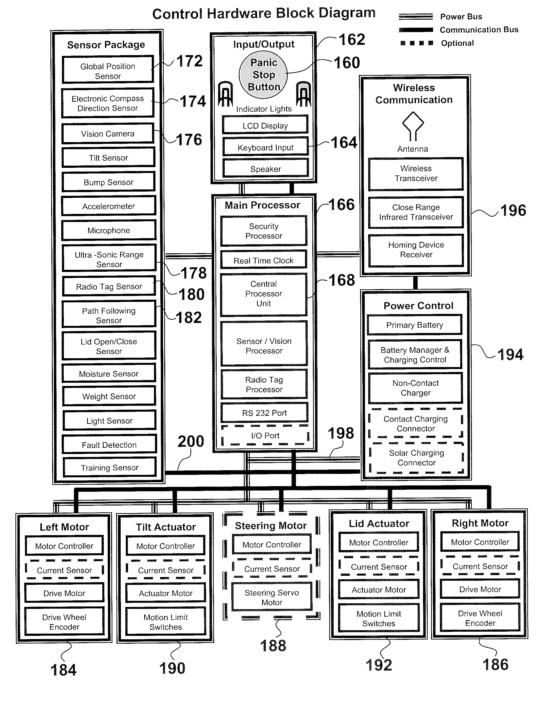
[0009]A rollout refuse container includes motive means for driving and steering a third wheel to permit locomotion of the refuse container along the ground. A tracking unit, which may be based upon any of several types of tracking systems, provides guidance for travel of the refuse container from a parking location to a location for pick up by a refuse collection truck and return to the parking location. Alternatively, a swiveling third wheel may be incorporated and a pair of driving wheels are independently actuated to provide both locomotion and steering by modifying the rate of rotation of one driving wheel with respect to the other. A further embodiment may incorporate a pair of driving tracks on opposed sides of the refuse container to provide locomotion and steering by differential speed of the driving tracks. To assist a three wheeled refuse container to traverse soft ground, the wheels may be wide or incorporate balloon tires to increase the footprint of each wheel and thereby reduce the possibility of the refuse container becoming mired.
[0010]It is therefore a primary object of the present invention to provide an automated self propelled refuse container capable of independent travel from a parking location to a location for pick up by a refuse collection truck and return to the parking location.
[0011]Another object of the present invention is to provide motive means and tracking means useable in conjunction with conventional refuse container to automate travel and tracking of such a refuse container.
[0012]Yet another object of the present invention is to provide a low cost self propelled automated refuse container by modifying an existing widely used refuse container to incorporate a drive mechanism and a tracking system.

Problems solved by technology

However, those with physical handicaps or of limited strength may have great difficulty in moving a filled refuse container to the curb and bringing back the emptied refuse container.
If the driveway is inclined, the difficulty of moving the refuse container is exacerbated.
If the driveway is inclined downwardly toward the curb, it requires a significant amount of strength to keep the refuse container from rolling too fast and going out of control.
To pull an emptied refuse container up a driveway may create difficulty.
However, such systems are generally not of commercial merit as the refuse containers are non standard compared to the types of refuse containers presently widely used throughout the country in combination with refuse collection trucks having specifically configured gripping arms and mechanisms for lifting, emptying and returning the refuse containers to the curb.

Method used


Image

  • Automated self powered waste container
  • Automated self powered waste container
  • Automated self powered waste container

Examples


Embodiment Construction

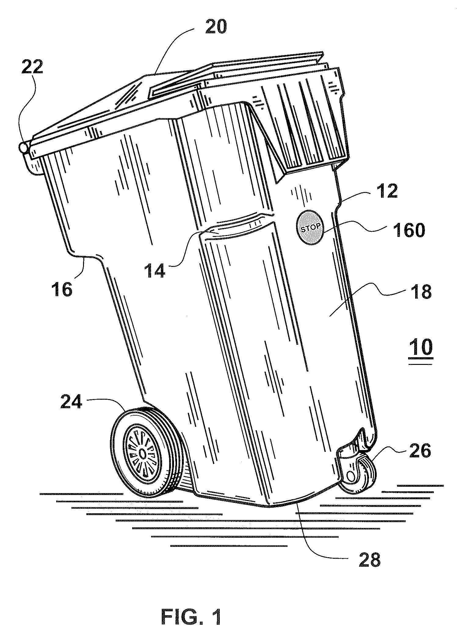
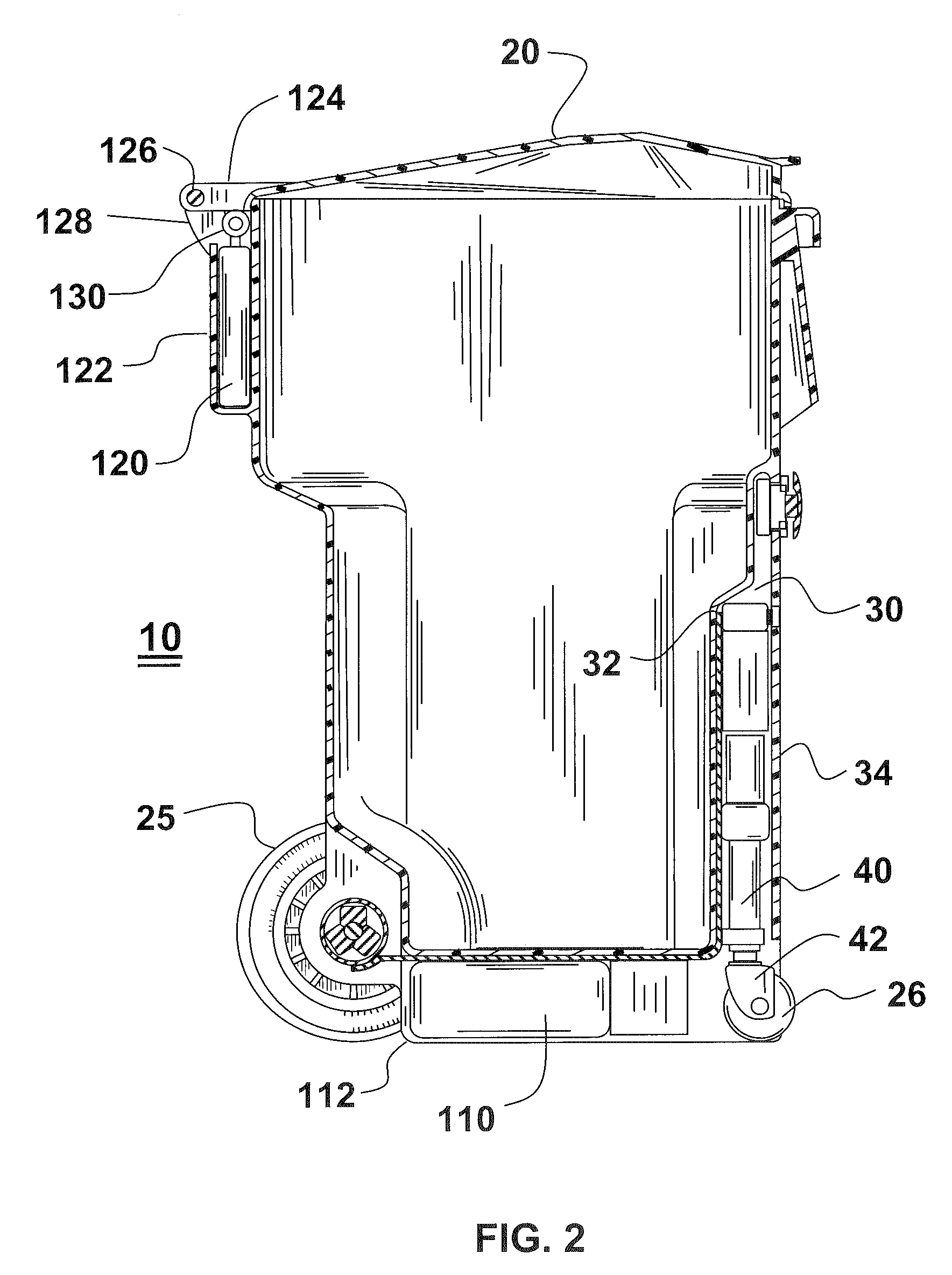
[0036]Referring to FIG. 1, there is shown rollout a refuse container 10 which is essentially of the conventional type that is widely used with garbage trucks having apparatus for lifting, emptying and lowering the refuse container. More particularly, the garbage trucks have a pair of curved arms which are actuated to grip refuse container 10 below shoulders 12, 14 and 16 and a further shoulder like shoulder 16 at the diametrically opposed side from shoulder 14. Front 18 of the refuse container faces the garbage truck upon engagement by the curved arms. The pair of curved arms close to grip the container and are then raised along a track. The track has a curve toward the bin of a garbage truck such that the refuse container is caused to rotate to a point close to vertical. Upon such rotation, lid 20 of the refuse container pivots about a hinge at the rear to expose the upper opening of the refuse container and permit the refuse to slide out of the refuse container and into the bin of...


PUM


Abstract

An automated self propelled refuse container travels from a parking or storage location to a refuse discharge location and return in response to a control unit cooperating with a tracking unit to control the direction of travel. Power is provided by an electric motor associated with each of two driving wheels rotating at the same rate and a third steering wheel provides stability and control over the direction of travel. The two driving wheels may rotate at a constant rate for straight line travel or charge direction, respectively, and a castering wheel provides stability and accommodates the direction of travel. Alternatively, a single wheel can provide both motive power and steering capability under control of a control unit responsive to the tracking unit and a pair of free wheeling wheels provide stability.

Description

CROSS REFERENCE TO RELATED APPLICATIONS[0001]The present application is related to a provisional patent application entitled “Automated Trash Can” filed Nov. 2, 2005 and assigned Ser. No. 60 / 732,872 and describing an invention invented by the present inventor.BACKGROUND OF THE INVENTION[0002]1. Field of the Invention[0003]The present invention relates to rollout refuse containers that travel automatically from a parking location to a curb for mechanical pick up and emptying by a garbage truck and return empty to the parking location.[0004]2. Description of Related Prior Art[0005]Conventional and widely used waste or refuse containers are of a molded plastic material having a hinged lid and four to five feet tall. Such a container includes a pair of wheels at the back side beneath a bar useable to pull the container by rolling it along the ground. Upon righting the container, the bottom edge of the front side rests on the ground and provides sufficient frictional contact with the gro...

Claims


Application Information

Patent Timeline
Patent Type & Authority Applications(United States)
IPC IPC(8): G06F19/00
CPCB65F1/1473B65F1/1638B65F1/141B65F2210/168
Inventor BROWN, ROHN A.
Owner SONY CORP
Learn More