Robot apparatus and control method therefor

a robot and control apparatus technology, applied in the direction of electric programme control, program control, instruments, etc., can solve the problems of reducing working efficiency, difficult for people to predict its motion, etc., and achieve the effect of improving work safety and high working efficiency

Inactive Publication Date: 2008-06-12
KK TOSHIBA
View PDF9 Cites 10 Cited by
  • Summary
  • Abstract
  • Description
  • Claims
  • Application Information

AI Technical Summary

Benefits of technology

[0011]The present invention provides a robot apparatus which can improve work safety while ensuring high working efficiency and a control method for the robot apparatus.

Problems solved by technology

Since an arm with a plurality of joints, in particular, is complex in motion, it is difficult for people to predict its motion.
Accordingly, it is conceivable that a sudden motion of a robot may cause an accident.
However, conventional methods such as one for activating a safety device after contact (collision) and one for always slowly moving an arm with a possible collision in mind may both lead to a reduction in working efficiency.

Method used


Image

  • Robot apparatus and control method therefor
  • Robot apparatus and control method therefor
  • Robot apparatus and control method therefor

Examples


Embodiment Construction

[0033]An embodiment of the present invention will be explained below with reference to the drawings.

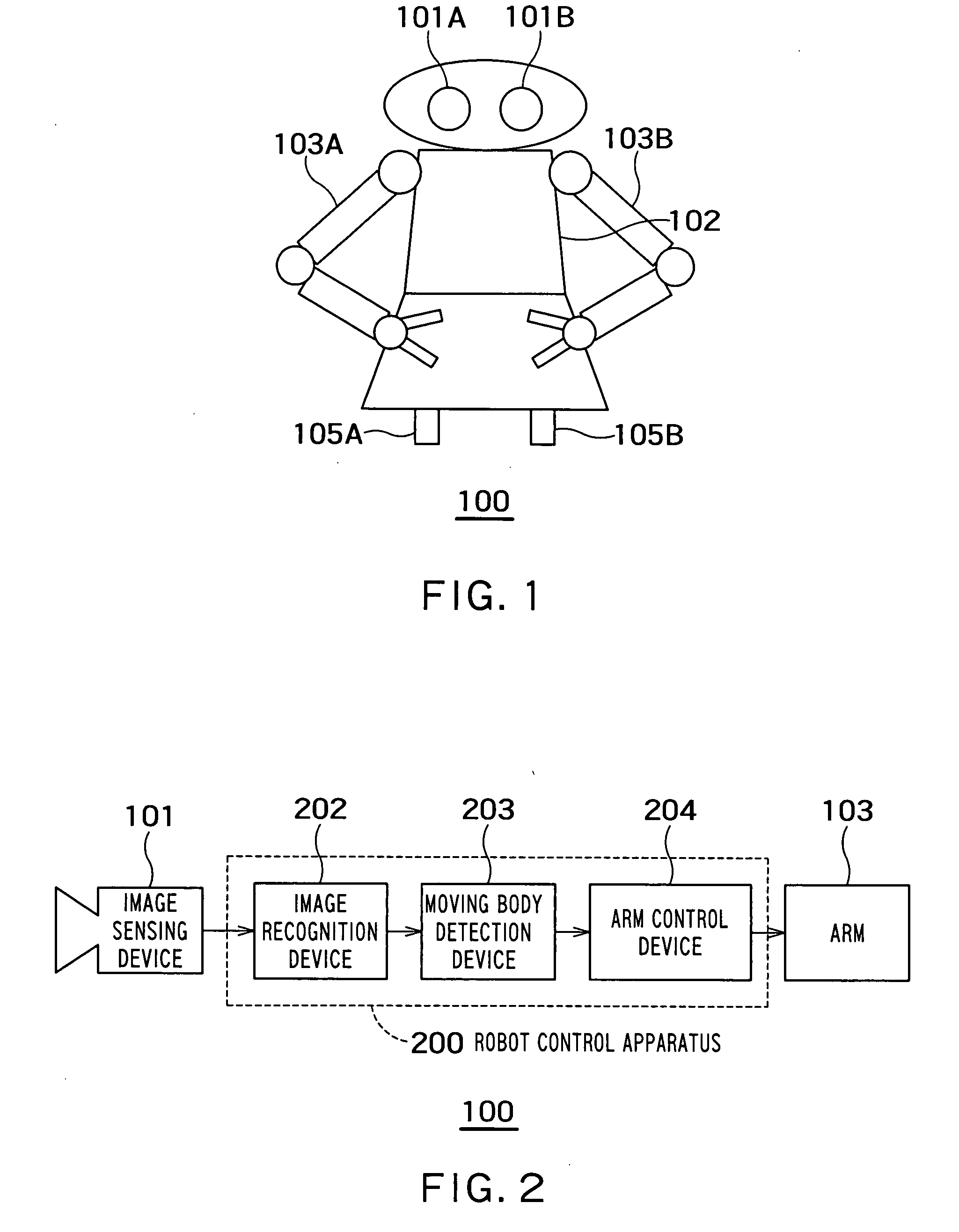
[0034]This embodiment will be explained taking, as an example, a robot 100 which has a main body unit (immovable unit) 102 equipped with arms 103A and 103B, image sensing devices 101A and 101B set in its head, and moving devices 105A and 105B, as shown in FIG. 1.

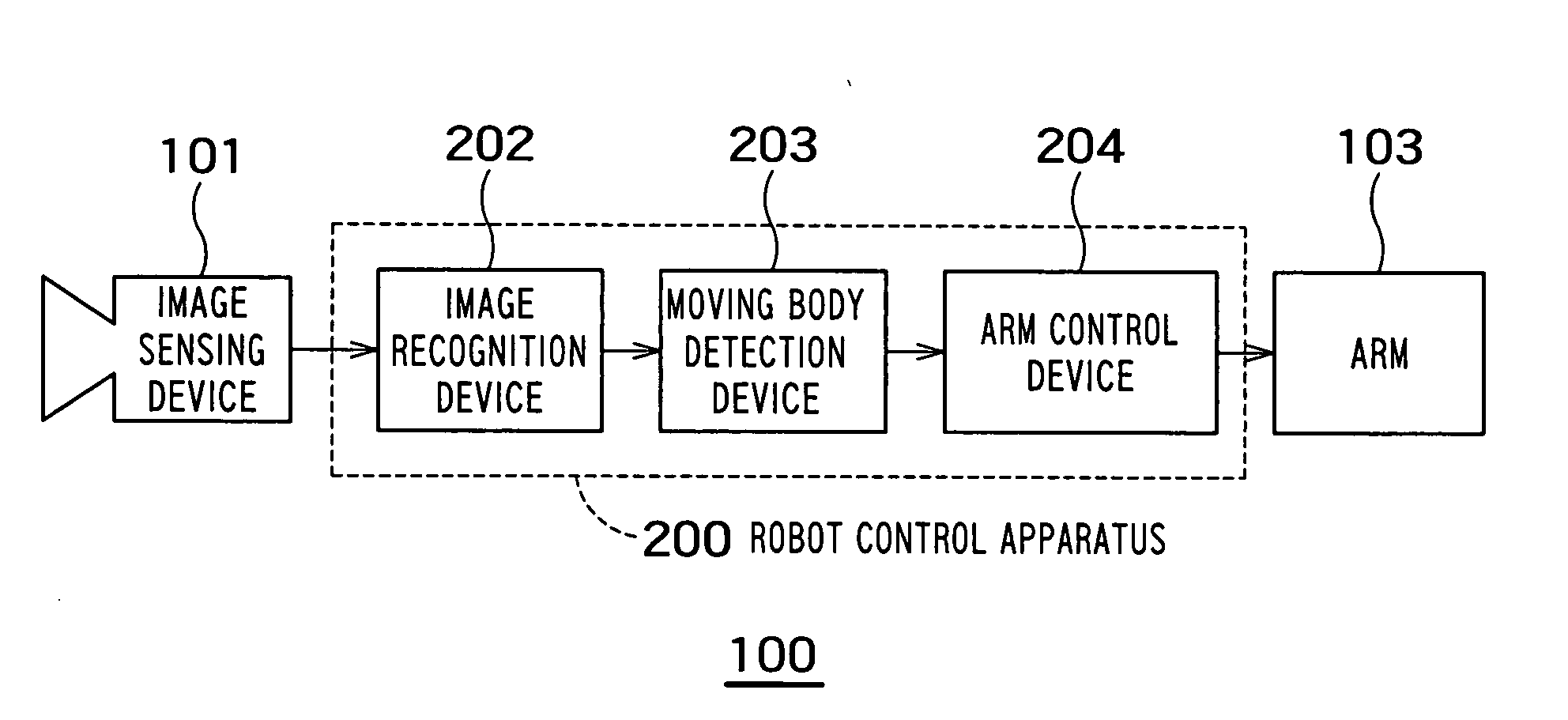
[0035]The components of a robot control apparatus according to this embodiment are all incorporated in the robot 100. FIG. 2 shows a block diagram of the robot 100 having the robot control apparatus 200.

[0036]Referring to FIG. 2, an image sensing device 101 acquires an image of the work space for an arm 103. The image sensing device 101 is a conventional CCD or CMOS camera. The image is acquired as a set of digital values including the value of luminance of each pixel and values representing a color such as an RGB color. The color mode (color / monochrome) and size of the captured image depend on the details of processing in an ...


PUM


Abstract

There is provided a robot apparatus which can improve work safety while ensuring high working efficiency and a control method for the robot apparatus. The robot apparatus includes a moving body detection unit which generates a predicted moving range for a movable unit region by predicting a range within which the movable unit region moves using a plurality of images sequentially sensed by an image sensing unit and attempts to detect a moving body in the predicted moving range and a control unit which, if a moving body is detected by the moving body direction unit, changes the operation of a movable unit.

Description

CROSS REFERENCE TO RELATED APPLICATIONS[0001]This application is based upon and claims the benefit of priority from the prior Japanese Patent Applications No. 2006-266822, filed on Sep. 29, 2006; the entire contents of which are incorporated herein by reference.BACKGROUND OF THE INVENTION[0002]1. Field of the Invention[0003]The present invention relates to a safety robot control apparatus mainly intended to, in a robot equipped with arms for work, prevent a collision of the robot with a nearby person using visual information.[0004]2. Related Art[0005]Numerous studies have conventionally been made on a method called visual feedback for, in work with arms of a robot, detecting a work object in an image and performing control using a three-dimensional position as a target position. The technique is expected to become essential for robots to perform complex work in human living space in the future.[0006]On the other hand, the possibility of a collision with a person increases with an in...

Claims


Application Information

Patent Timeline
Patent Type & Authority Applications(United States)
IPC IPC(8): G05B19/00
CPCG05B2219/39091B25J9/1674
Inventor NISHIYAMA, MANABU
Owner KK TOSHIBA
Why Eureka
Try Eureka