Audio Encoding Device, Audio Encoding Method, and Audio Encoding Program

a technology of audio encoding and audio encoding methods, applied in the field of audio encoding devices, audio encoding methods, audio encoding programs, to achieve the effects of reducing the amount of operation needed, high quality, and correcting the noise level of each sub-band

Active Publication Date: 2008-06-12
NEC CORP
View PDF12 Cites 33 Cited by
  • Summary
  • Abstract
  • Description
  • Claims
  • Application Information

AI Technical Summary

Benefits of technology

[0043]The present invention makes it possible to calculate a correction coefficient based upon importance of auditory sense of an input signal, thereby to correct a noise level of each sub-band.
[0044]Further, a normal-resolution frequency analysis is made in calculating the correction coefficient of the present invention, whereby the noise level of the sub-band into which importance of auditory sense has been reflected can be obtained while reducing the operation amount necessary for the high-resolution frequency analysis. As a result, it becomes possible to realize the audio encoding device with a high quality.

Problems solved by technology

However, in a case of having lowered the bit rate, for example, to an extent of 48 kbps, the band enabling the acoustic signal to be encoded at a high quality becomes 10 kHz or so, or less, and the sound is reproduced of which a high-frequency-band signal component is subjectively insufficient in an auditory sense.

Method used


Image

  • Audio Encoding Device, Audio Encoding Method, and Audio Encoding Program
  • Audio Encoding Device, Audio Encoding Method, and Audio Encoding Program
  • Audio Encoding Device, Audio Encoding Method, and Audio Encoding Program

Examples


first embodiment

[0084]At first, a first embodiment will be explained.

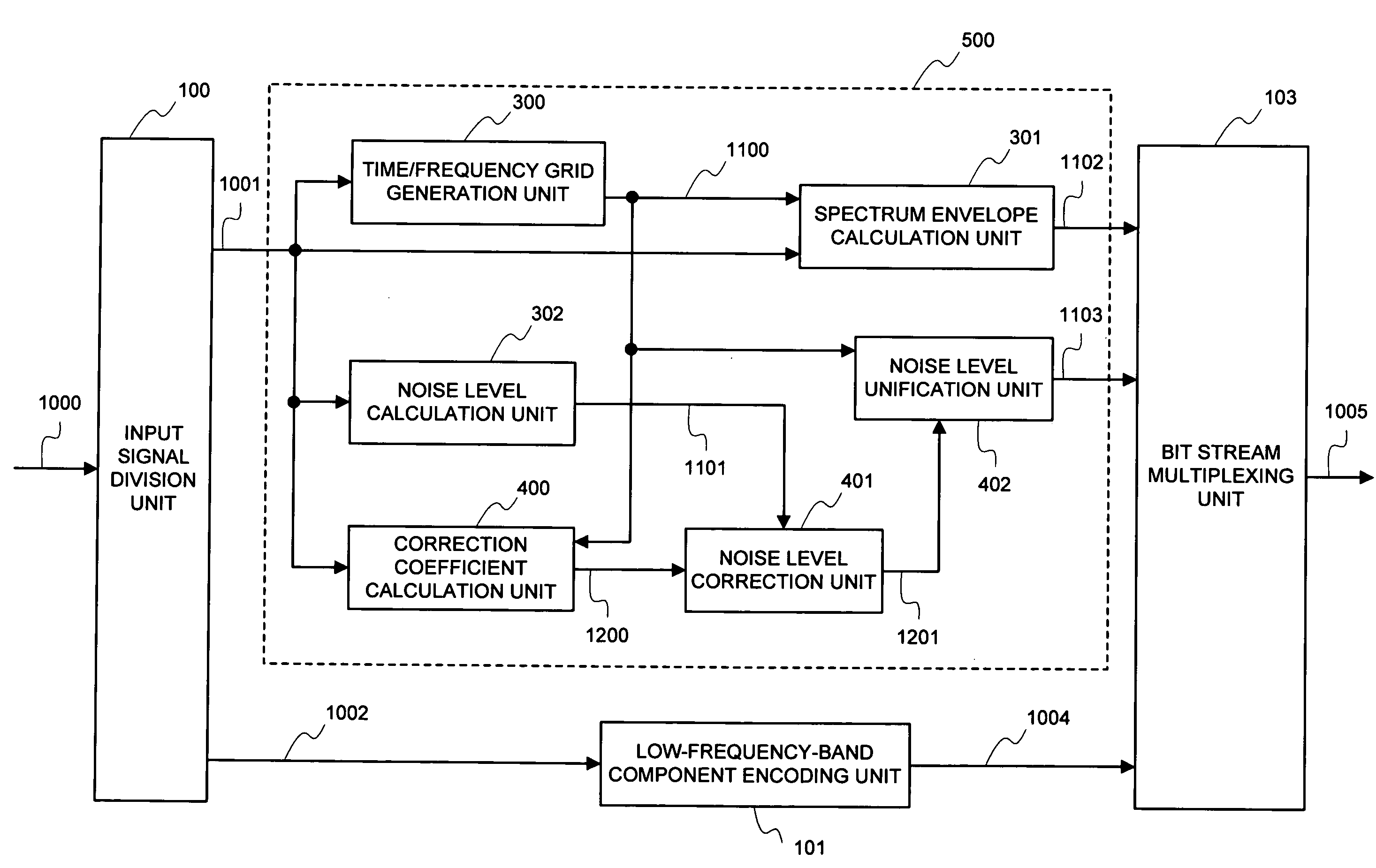
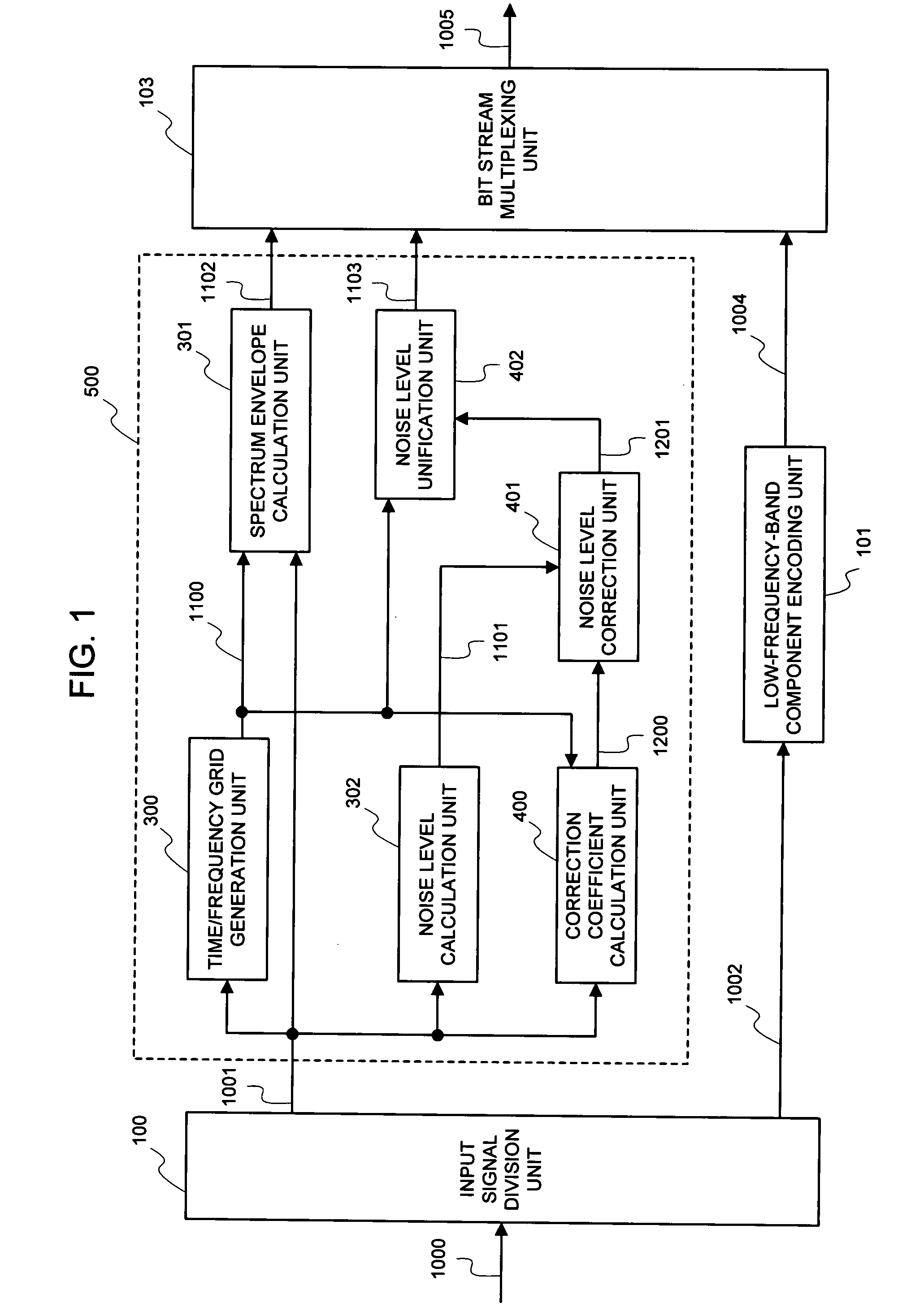
[0085]Upon making a reference to FIG. 1, the audio encoding device of the first embodiment of the present invention is configured of an input signal division unit 100, a low-frequency-band component encoding unit 101, a time / frequency grid generation unit 300, a spectrum envelope calculation unit 301, a noise level calculation unit 302, a correction coefficient calculation unit 400, a noise level correction unit 401, a noise level unification unit 402, and a bit stream multiplexing unit 103. FIG. 1 and FIG. 6 differ from each other in a high-frequency-band component encoding unit 102 and a high-frequency-band component encoding unit 500. Upon further comparing these components in details by employing FIG. 1 and FIG. 7, the correction coefficient calculation unit 400 and the noise level correction unit 401 are added to the high-frequency-band component encoding unit 500, and the noise level unification unit 300 is replaced by the n...

second embodiment

[0103]Next, the present invention will be explained in details by employing FIG. 4.

[0104]Upon making a reference to FIG. 4, the best mode for carrying out the second invention of the present invention includes an input signal division unit 100, a low-frequency-band component encoding unit 101, a time / frequency grid generation unit 300, a spectrum envelope calculation unit 301, a noise level calculation unit 302, a correction coefficient calculation unit 403, a noise level correction unit 401, a noise level unification unit 402, and a bit stream multiplexing unit 103.

[0105]The second embodiment of the present invention differs in only that the correction coefficient calculation unit 400 is replaced with the correction coefficient calculation unit 403 as compared with the first embodiment of the present invention, and the other part thereof is entirely identical. Thereupon, the correction coefficient calculation unit 403 will be explained in details.

[0106]The correction coefficient ca...

third embodiment

[0109]Next, the present invention will be explained in details by making a reference to the accompanied drawings.

[0110]Upon making a reference to FIG. 5, in the case of having configured the foregoing first and second embodiments of the present invention with a program 601, the third embodiment of the present invention is equivalent to a configuration of a computer 600 that operates under its program 601.

[0111]The program 601, which is loaded into the computer 600 (central processing unit; a processor; a data processing unit), controls an operation of the computer 600 (central processing unit; a processor; a data processing unit). The computer 600 (central processing unit; a processor; a data processing unit) executes the process identical to the process explained in the foregoing first and second inventions of the present invention under a control of the program 601, and outputs the bit stream 1005 from the input signal 1000.


PUM


Abstract

By using a high-range sub-band signal, a correction coefficient corresponding to importance of auditory sense is calculated to correct a noise level and generate additional signal information, thereby accurately reflecting the noise level of the sub-band important in the auditory sense. Thus, it is possible to calculate additional signal information reflecting the noise level of the sub-band important in the auditory sense according to importance with a small calculation amount. The calculation amount can further be reduced by using a correction coefficient based on the characteristic of an ordinary audio signal.

Description

APPLICABLE FIELD IN THE INDUSTRY[0001]The present invention relates to an audio encoding device, an audio encoding method, and an audio encoding program, and more particularly to an audio encoding device, an audio encoding method, and an audio encoding program that allow a wide-band audio signal to be encoded with a small information amount at a high quality.BACKGROUND ART[0002]The method of utilizing band division encoding is widely known as a technology capable of encoding an ordinary acoustic signal with a small information amount, and yet obtaining a reproduction signal with a high quality. As a representative example of the encoding utilizing such a band division, there exists MPEG-2AAC (Moving Experts Group 2 Advance Audio Coding), being ISO / IEC International Standard, in which a wide-band stereo signal of 16 kHz or more can be encoded in a bit rate of 96 kbps or so at a high quality.[0003]However, in a case of having lowered the bit rate, for example, to an extent of 48 kbps,...

Claims


Application Information

Patent Timeline
Patent Type & Authority Applications(United States)
IPC IPC(8): G10L19/00G10L19/02G10L19/20G10L21/038G10L21/0388
CPCG10L19/0208G10L21/038G10L19/20
Inventor SHIMADA, OSAMU
Owner NEC CORP
Why Eureka
Try Eureka