Framed Opening Bracing System

Inactive Publication Date: 2008-06-19
COOK CHARLIE E
View PDF7 Cites 13 Cited by
  • Summary
  • Abstract
  • Description
  • Claims
  • Application Information

AI Technical Summary

Benefits of technology

[0012]In light of the prior art, the present invention answers a long felt need in the art by providing an improved framed opening bracing device that is versatile, compact, lightweight, durable, fine tunable, and economical.
[0015]Related to its versatility is the invention's compact, minimalist size concept. Rather than utilizing bulky rigid frames or cumbersome blocks, the present invention accomplishes framed opening stability bracing through secured angled supports. Some jobs may require only a single brace and others may require multiple braces. Thus, the contractor is not pigeon holed into a single rigid design but can use as many of the independent supports as necessary. Importantly, these supports do not block the opening even when multiple supports are utilized in order to secure a particular frame. For instance, supports can be attached to the top of the frame or the sides while the central opening remains relatively free and open for light, air, and objects to pass. A double door opening may require even more support which is accommodated under the present invention by applying additional copies of the device with various attachment points as necessary.
[0016]Another feature of the invention that adds to its versatility is its lightweight. The invention is designed to be lightweight so that it can be easily transported from opening to opening and from jobsite to jobsite. Moreover, multiple copies of the invention may be easily carried by a single worker as required for a particular job.
[0019]Because of many of the above features, the design of the present invention is quite cost effective. No longer must wasteful traditional wooden supports be constructed and then deconstructed for each framed opening because the present invention is completely reusable. Moreover, the simplicity lowers the learning curve for installation that is applicable to many different types and sizes of framed openings.

Problems solved by technology

Moreover, if the frame is out of plumb once the masonry has set, the windows or doors will not install or function properly and the frame cannot be readjusted without rather extreme measures.
Thus, this traditional method of brace construction is very wasteful in terms of time, money, and materials because the contractor spends time and money purchasing the wood, custom crafts the supports to fit the particular opening, and then discards the wood after each frame and wall has been completed.
This waste has negative effects on the contractors' bottom line as well as on the Earth's environment.
The rigid frame of the Ruff invention is bulky and difficult to transport.
It is expensive to make and use relative to the traditional methods and it is difficult to teach unskilled workers how to use properly.
Importantly, the Ruff invention is attached to the door frame with screws which further complicate the process.
And, once these legs are constructed, they are limited as to support placement because of their relationship to the rigid frame.
The kit is rather bulky and while installed makes movement through the doorway impossible because the foam blocks span the width of the door.
Also, the kit of Kurfees is not designed to adjust and adapt to many different sizes of door frames and other openings such as framed vents.
Similarly, it is not suited to be used with windows as glass would prevent the attachment of the clamping mechanism.
Kurfees also lacks the ability to easily fine tune the lengths of the support braces and to easily fine tune the width of the clamping “holder” mechanism.
Importantly, the clamping or “holder” mechanism of Kurfees is not designed to accommodate the great varieties of door jam depths that occur in a construction environment.
The width of the J hook portion of either end of the holder is inherently limited such that, though the length may be adjusted, its width cannot accommodate varying depths of door jams.

Method used


Image

  • Framed Opening Bracing System
  • Framed Opening Bracing System
  • Framed Opening Bracing System

Examples


Embodiment Construction

[0026]It is to be understood by a person having ordinary skill in the art that the present discussion is a description of exemplary embodiments only, and is not intended as limiting the broader aspects of the present invention. The following example is provided to further illustrate the invention and is not to be construed to unduly limit the scope of the invention.

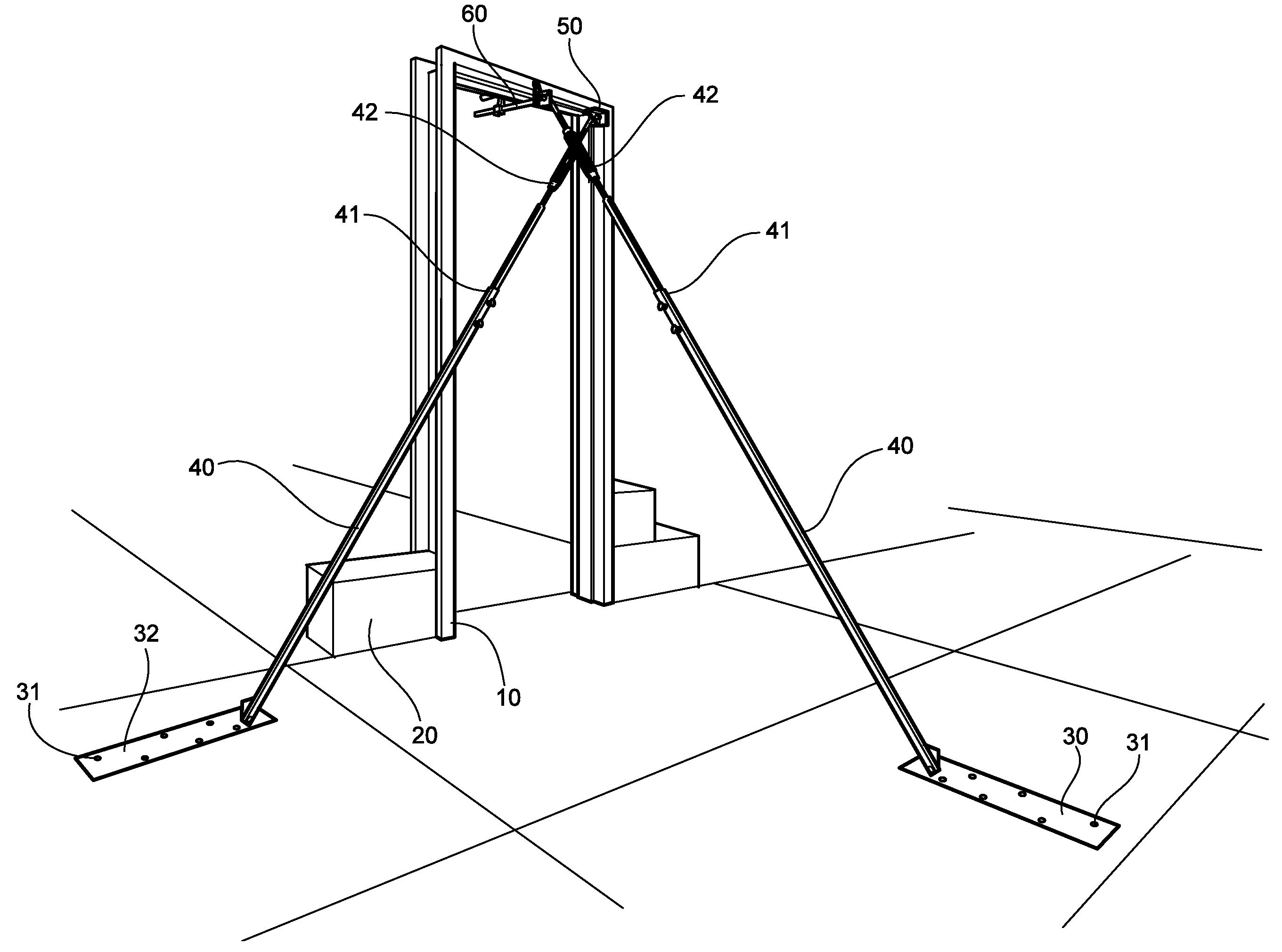
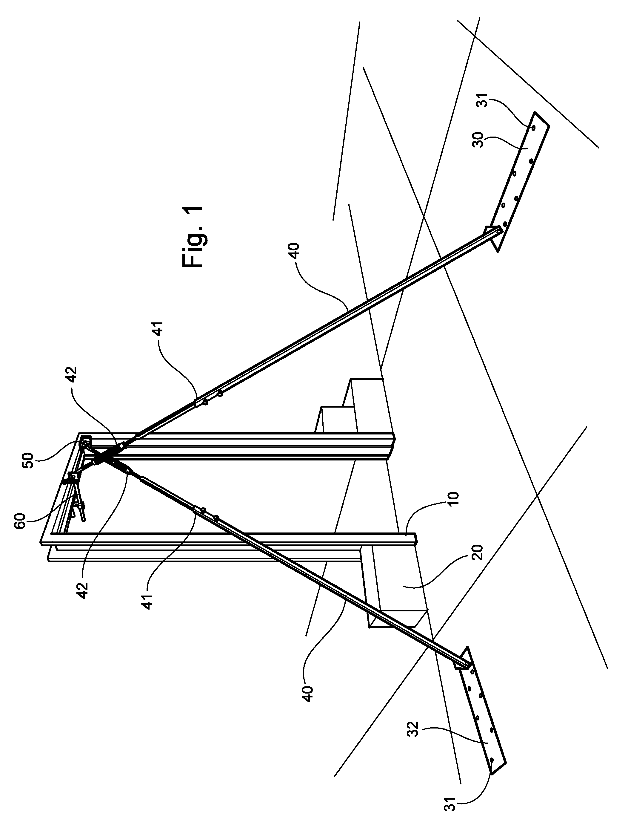
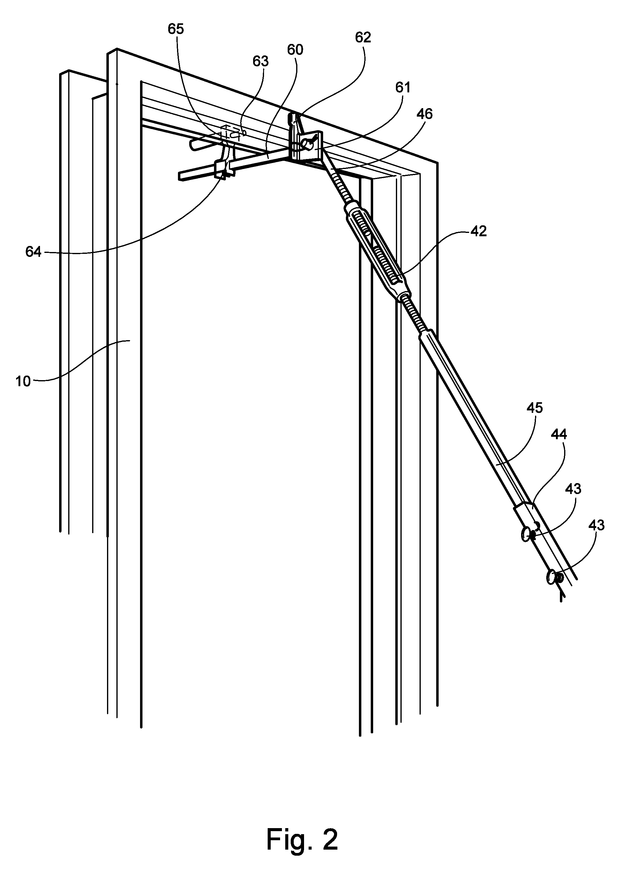
[0027]The present invention is a framed opening bracing system that utilizes one or more bracing arm devices to secure the frame during construction. The device of the present invention comprises a frame attachment means, a support arm (40), and a fixable base (30). The frame attachment means further consists of either a versatile clamp (60) or a corner support unit (50).

[0028]The versatile clamp (60) secures the bracing arm device to the frame (10). It is pivotally connected to the support arm (40) and temporarily attaches to the frame (10) by means of compression applied to the facial surfaces of the frame (10). This at...


PUM


Abstract

The invention is a framed opening bracing system. The invention features frame bracing devices which attach to the framed opening and to the flooring or other surface of a construction job site. The devices attach to the frame via a versatile clamp unit or a corner support unit and extend to the floor via bracing arms. The corner support unit attaches via pressure applied at an angle to the frames corner and the versatile clamp unit attaches via pressure applied to the facings of the frame. The arms feature two levels of adjustment, a relative distance adjustment and a fine tune distance adjustment, which can be manipulated to set a framed opening to plumb and to keep the frame securely in place during wall construction.

Description

RELATED APPLICATIONS[0001]Not applicable.FEDERALLY SPONSORED RESEARCH OR DEVELOPMENT[0002]Not applicable.REFERENCED OR INCORPORATED MATERIAL[0003]Not applicable.BACKGROUND OF INVENTION[0004]The present invention is related to the field of construction and specifically to framed openings necessary in masonry construction such as windows and doors which are integral to masonry walls. Particularly, the invention is directed to a device used to brace such framed openings in masonry wall construction.[0005]In the art of masonry wall construction, it is quite common, especially in commercial applications, for any openings necessary in the walls to be framed-in prior to the construction of the wall. As such, contractors erect door and window frames by utilizing temporary bracing outside the plane of the wall, and then erect the masonry wall block by block around the frame. Therefore, the frames are put into place before the walls are built.[0006]During the wall construction, it is extremel...

Claims


Application Information

Patent Timeline
IPC IPC(8): E04G21/12E04C5/12E04H12/24F16B7/06E04G21/26
CPCY10T403/295E04G21/1841E04G21/1858
Inventor COOK, CHARLIE E.
Owner COOK CHARLIE E
Why Eureka
Try Eureka