
Data interface assembly for electronic locks and readers

a technology of data interface and electronic locks, applied in the field of electronic locks, can solve the problems of unreliable solder joints, pcb integrity risk, and interface arrangements often experiencing malfunctions

Active Publication Date: 2008-06-19
HARROW PRODS
View PDF36 Cites 10 Cited by
  • Summary
  • Abstract
  • Description
  • Claims
  • Application Information

AI Technical Summary

Benefits of technology

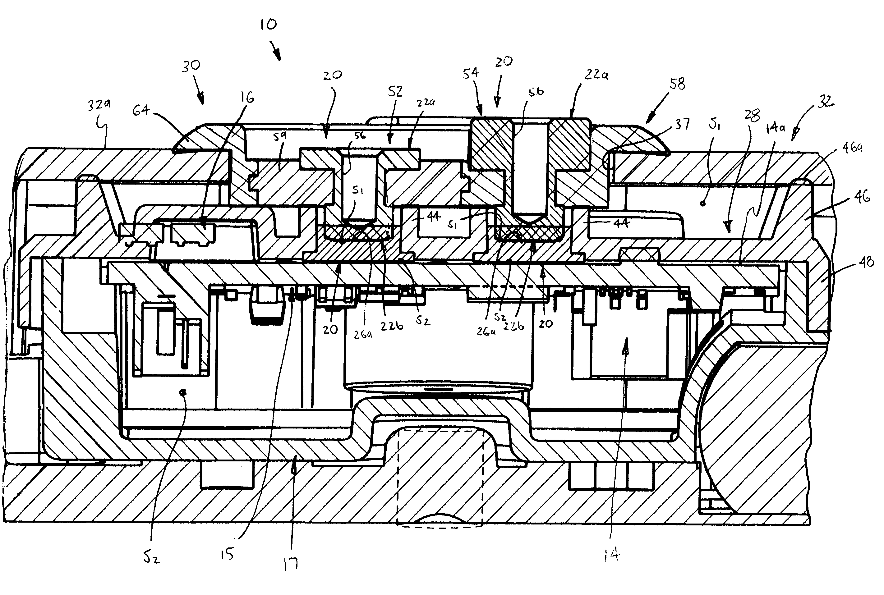
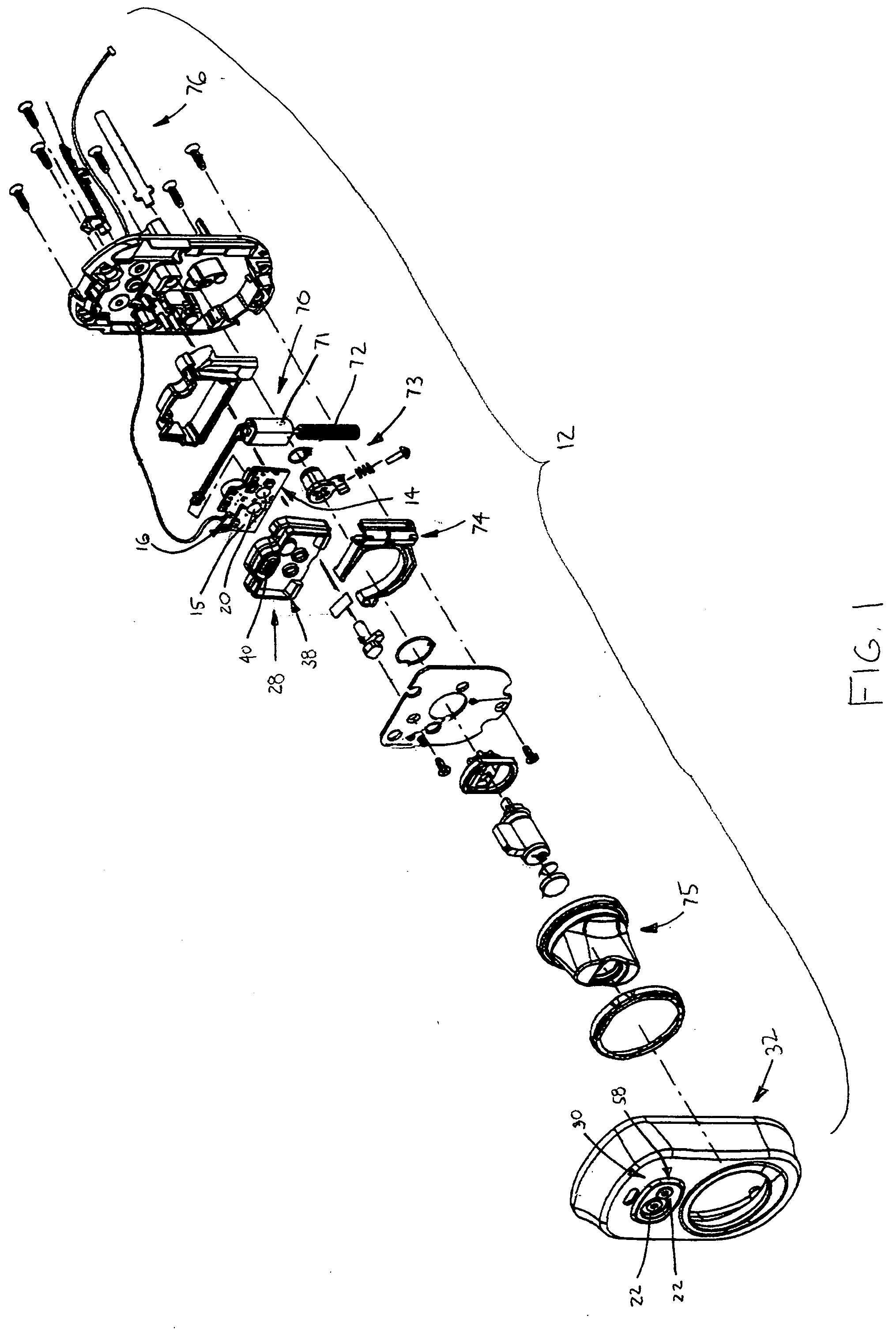
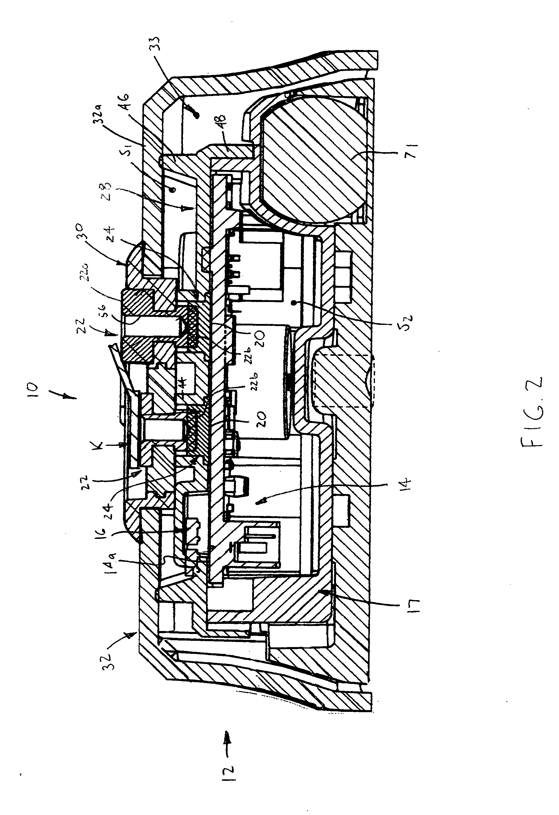
[0002]Data interface assemblies, such as input and / or output assemblies for electronic locks or electronic readers, are known. Certain types of data interface assemblies include a data port and a contact on a PCB, and in some of these devices also include a conductor disposed between and electrically coupling the port and the contact. When directly connected with a PCB contact, the ports are typically soldered thereto, which often leads to unreliable soldered joints and risks the integrity of the PCB by mechanical loads transferred from the data port. In other applications, wires, prongs, springs, etc. have been used to connect a data port with the PCB contact spaced therefrom, which eliminates mechanical loading of the contact and direct soldering between port and contact. However, such interface arrangements often experienced malfunctions due to pinched wires and generally required some manner of waterproofing the PCB to prevent moisture damage.SUMMARY OF THE INVENTION

Problems solved by technology

When directly connected with a PCB contact, the ports are typically soldered thereto, which often leads to unreliable soldered joints and risks the integrity of the PCB by mechanical loads transferred from the data port.
However, such interface arrangements often experienced malfunctions due to pinched wires and generally required some manner of waterproofing the PCB to prevent moisture damage.

Method used


Image

  • Data interface assembly for electronic locks and readers
  • Data interface assembly for electronic locks and readers
  • Data interface assembly for electronic locks and readers

Examples


Embodiment Construction

[0014]Certain terminology is used in the following description for convenience only and is not limiting. The words “right”, left”, “lower”, “upper”, “upward”, “down”and “downward” designate directions in the drawings to which reference is made. The words “inner”, “inwardly” and “outer”, “outwardly” refer to directions toward and away from, respectively, a designated centerline or a geometric center of an element being described, the particular meaning being readily apparent from the context of the description. Further, as used herein, the word “connected” is intended to include direct connections between two members without any other members interposed therebetween and indirect connections between members in which one or more other members are interposed therebetween. The terminology includes the words specifically mentioned above, derivatives thereof, and words of similar import.

[0015]Referring now to the drawings in detail, wherein like numbers are used to indicate like elements t...


PUM


Abstract

An interface assembly is for an electronic device including a base and a control on the base and includes a contact on the base and coupled with the control and a data port spaced from the contact. A conductor is disposed between the data port and the contact such that data is transmissible between the data port and the contact through the conductor. The conductor is generally compressed or / and compressible between the data port and the contact and is formed of a conductive carbon material. The data port is spaced from the contact by a distance within a range of values, and the conductor provides a conductive path between the data port and the contact at each spacing distance value. A fluid impermeable cover is disposed over the base and covers the control and the contact to prevent moisture from contacting these components, with the conductor extending through the cover.

Description

[0001]The present invention relates to electronic locks, and more particularly to data interface assemblies for such electronic locks.[0002]Data interface assemblies, such as input and / or output assemblies for electronic locks or electronic readers, are known. Certain types of data interface assemblies include a data port and a contact on a PCB, and in some of these devices also include a conductor disposed between and electrically coupling the port and the contact. When directly connected with a PCB contact, the ports are typically soldered thereto, which often leads to unreliable soldered joints and risks the integrity of the PCB by mechanical loads transferred from the data port. In other applications, wires, prongs, springs, etc. have been used to connect a data port with the PCB contact spaced therefrom, which eliminates mechanical loading of the contact and direct soldering between port and contact. However, such interface arrangements often experienced malfunctions due to pin...

Claims


Application Information

Patent Timeline
IPC IPC(8): G06K7/06
CPCE05B13/10E05B13/101E05B47/0012G07C2009/00761E05B47/0676E05B2047/0031G07C9/00944E05B47/0657Y10T70/7136
Inventor WALSH, JOHN E.MILLER, KEVIN DEAN
Owner HARROW PRODS
Learn More