Hydroelectric generating station and method of constructing same

a technology of hydroelectric generating station and generating station, which is applied in the direction of electric generator control, instruments, machines/engines, etc., can solve the problems of large, expensive, and relative heavyness, and achieve the effect of reducing the risk of avoiding failure to reach the maximum flood elevation

Active Publication Date: 2008-06-19
OBERMEYER HENRY KARL
View PDF10 Cites 13 Cited by
  • Summary
  • Abstract
  • Description
  • Claims
  • Application Information

AI Technical Summary

Benefits of technology

[0006]It is an object of this invention to provide a low-cost alternative to both conventional hydroelectric generating plants and hydroelectric generating plants that may be installed into upstream stop log slots. It is a furt...

Problems solved by technology

U.S. Pat. No. 4,319,142 to Mayo et al discloses an apparatus which can utilize all of the head at certain preexisting st...

Method used


Image

  • Hydroelectric generating station and method of constructing same
  • Hydroelectric generating station and method of constructing same
  • Hydroelectric generating station and method of constructing same

Examples


Embodiment Construction

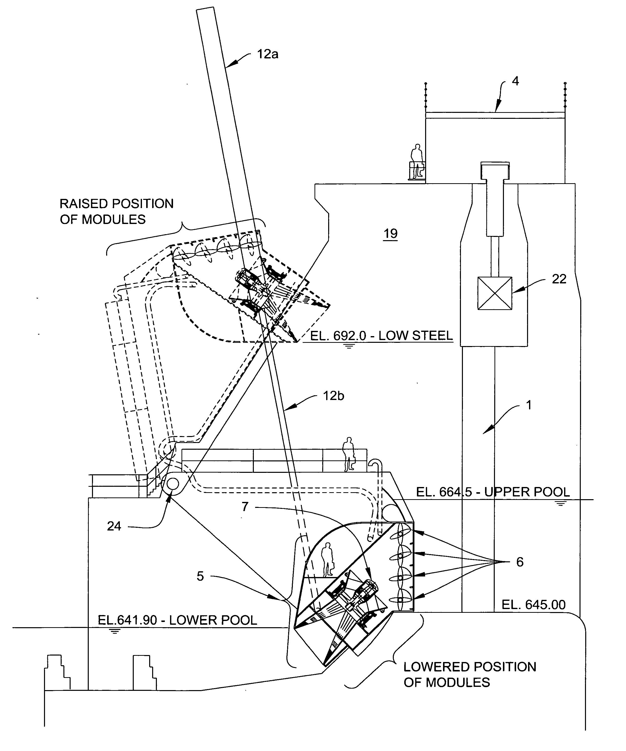
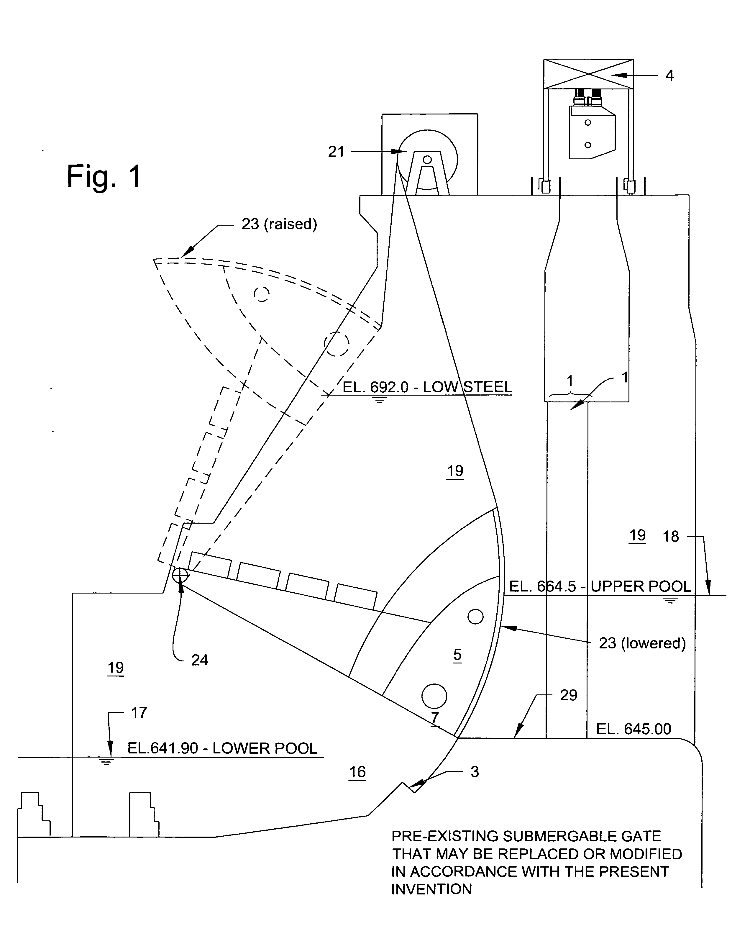
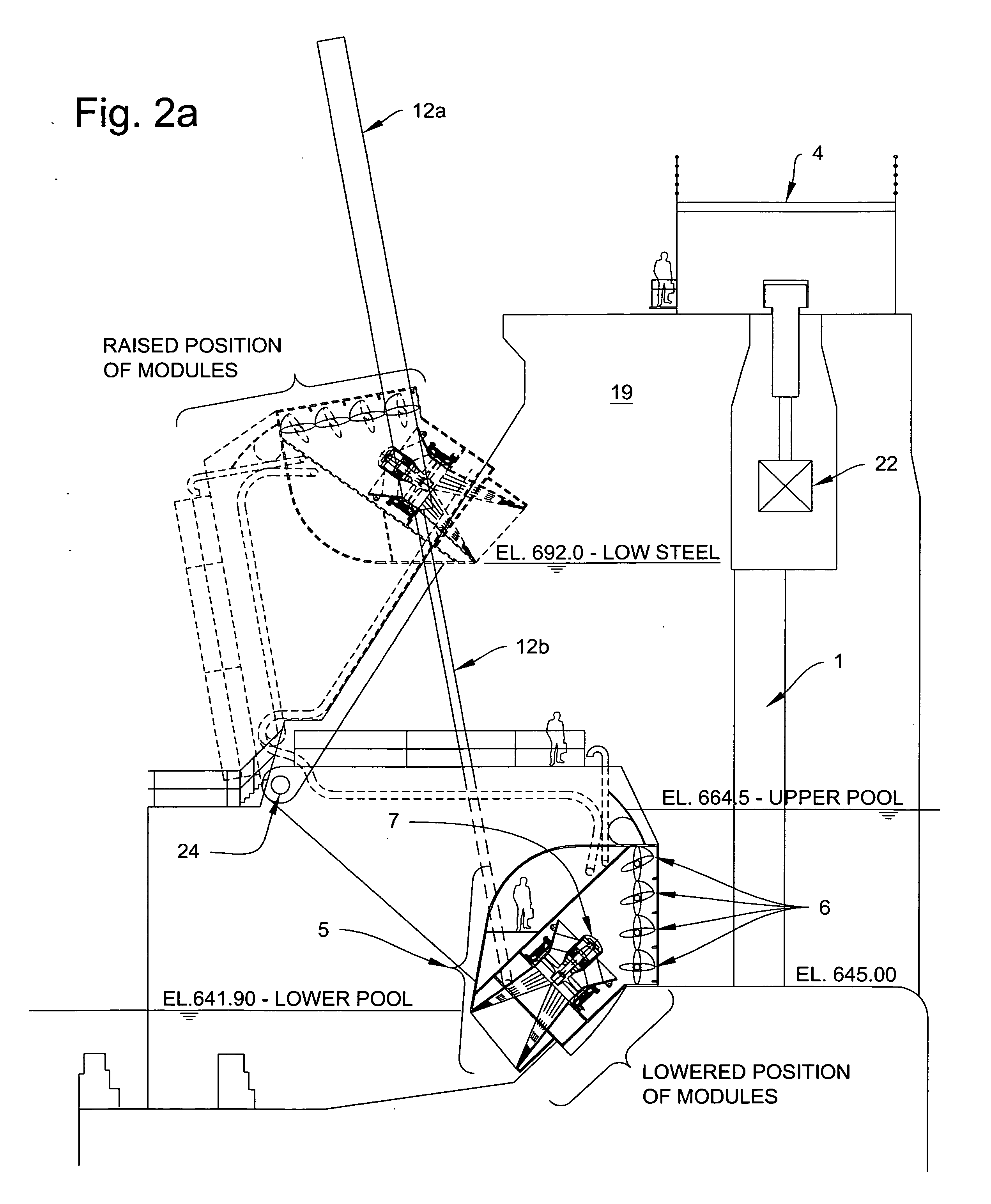
[0039]Referring to FIG. 1, a prior art pre-existing submergible radial gate 23 with gate pivots 24 at New Cumberland Locks and. Dam is shown in sectional elevation in both raised (dotted lines) and lowered (solid lines) positions. The gate sill 29 is at elevation 645 ft and is above the lower pool, or tailwater, elevation of 641.9 ft, making it impossible for a turbine generator array fitted to the stop-log slot 1 to utilize the full available head of 22.6 ft (upper pool elevation minus lower pool elevation). Radial gate 2 is was originally designed to be lowered to bottom gate stop 3 in order to pass ice and floating debris over the top of the radial gate 2. Dashed lines indicate the profile of gate 23 when fully lowered against stop 3. A further issue with utilizing the stop log slots 1 for generating modules 5 (in the figures that follow) is that the service bridge 4 limits the height to which a stop log slot installed generating module might be lifted above the specified “low st...


PUM

PropertyMeasurementUnit
Forceaaaaaaaaaa
Flow rateaaaaaaaaaa

Abstract

The invention relates to hydroelectric generating plants which may be prefabricated and subsequently exchanged for preexisting radial water control gates. The hydroelectric generating plant disclosed herein may be particularly advantageous for hydroelectric development of projects with preexisting submergible radial gates. Various configurations are disclosed which maximize generating capacity, hydraulic efficiency, and flood flow capacity, while minimizing weight and cost.

Description

[0001]This application is based upon and claims the benefit of my Provisional application No. 60 / 860,802, Filed Nov. 22, 2006.BACKGROUND OF THE INVENTION[0002]1. Field of Invention[0003]The present invention relates to hydroelectric generating facilities which may be constructed in conjunction with, or installed as a replacement for, radial water control gates. The hydroelectric generating apparatus disclosed herein may be particularly advantageous for generating power at submergible radial gates, examples of which were constructed at Meldahl Locks and Dam, New Cumberland Locks and Dam, Markland Lock and Dam, and McAlpine Lock and Dam on the Ohio River and Marseilles Lock and Dam on the Illinois River in the USA. The hydroelectric generating facilities and the methods of installation disclosed herein have many potential applications where preexisting gate structures can be converted into hydroelectric plants while avoiding the coffer-damming, dredging, excavation, geological and hyd...

Claims


Application Information

Patent Timeline
IPC IPC(8): F03B13/08G06Q10/00
CPCF03B13/08Y10T29/49009Y10T29/494Y02E10/22Y02E10/20
Inventor OBERMEYER, HENRY K.
Owner OBERMEYER HENRY KARL
Why Eureka
Try Eureka