Digital delay locked loop

a technology of delay lock and loop, applied in the direction of pulse automatic control, pulse manipulation, pulse technique, etc., can solve the problems of high power consumption, many inevitable problems, and the inability to develop a conventional delay lock b>100/b> to be highly integrated,

Inactive Publication Date: 2008-06-19
IND TECH RES INST
View PDF2 Cites 14 Cited by
  • Summary
  • Abstract
  • Description
  • Claims
  • Application Information

AI Technical Summary

Benefits of technology

[0010]The present invention provides a digital delay locked loop, which includes a plurality of controllable delay circuits connected in series, a phase detecting unit, and a delay control unit. Each of the controllable delay circuits transmits a specific period signal according to delay time determined by a delay control code. The phase detecting unit coupled to each of the controllable delay circuits samples the specific period signal at the transition points of the specific period signal transmitted by each of the controllable delay circuits, so as to generate a sample output code. The phase detecting unit determines the sample output code to provide a counting information. When the sample output code is a specific sample code, the digital delay locked loop remains in the locked state.
[0011]The delay control unit enables the delay control code to increase or reduce according to the counting information. The delay control unit, the controllable delay circuits, and the phase detecting unit form a feedback mechanism. Therefore, the digital phase locked loop keeps regulating the delay control code through the feedback mechanism until the locked state is assumed.
[0012]In another aspect, the present invention further provides a digital delay locked loop, for regulating a positive received signal to a phase locked signal. The digital delay locked loop includes a plurality of controllable delay circuits connected in series, a phase detecting unit, and a delay control unit. Each of the controllable delay circuits sequentially transmits the positive received signal and a negative received signal according to delay time determined by a delay control code, and the positive received signal and the negative received signal form a specific period signal. The phase detecting unit coupled to each of the controllable delay circuits samples the positive received signal at the transition points of the specific period signal transmitted by each of the controllable delay circuits. Then, the phase detecting unit provides a counting information or a locked information by judging the sample output code.
[0013]The delay control unit provides and regulates the delay control code according to the counting information and the locked information. The delay control unit, the controllable delay circuits, and the phase detecting unit form a feedback mechanism. Therefore, according to the counting information, the delay control unit keeps increasing or reducing the delay control code through the feedback mechanism until the digital delay locked loop remains in the locked state. The digital delay locked loop remains in the locked state according to the locked information, and uses one of the plurality of controllable delay circuits to generate a phase locked signal.

Problems solved by technology

However, the conventional delay locked loop 100 adopts a mixed-mode design, which incurs many inevitable problems.
For example, the conventional delay locked loop 100 cannot be developed to be highly integrated, and is quite sensitive to variations of process parameters including voltage and temperature.
In addition, as the locked time of the conventional delay locked loop 100 is too long, so the power consumption will be excessively high.

Method used


Image

  • Digital delay locked loop
  • Digital delay locked loop
  • Digital delay locked loop

Examples


Embodiment Construction

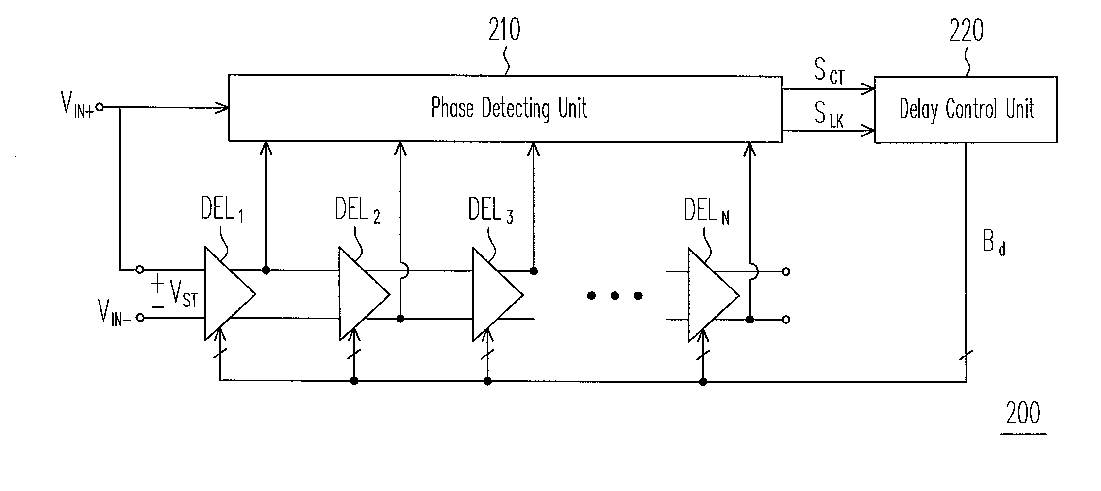
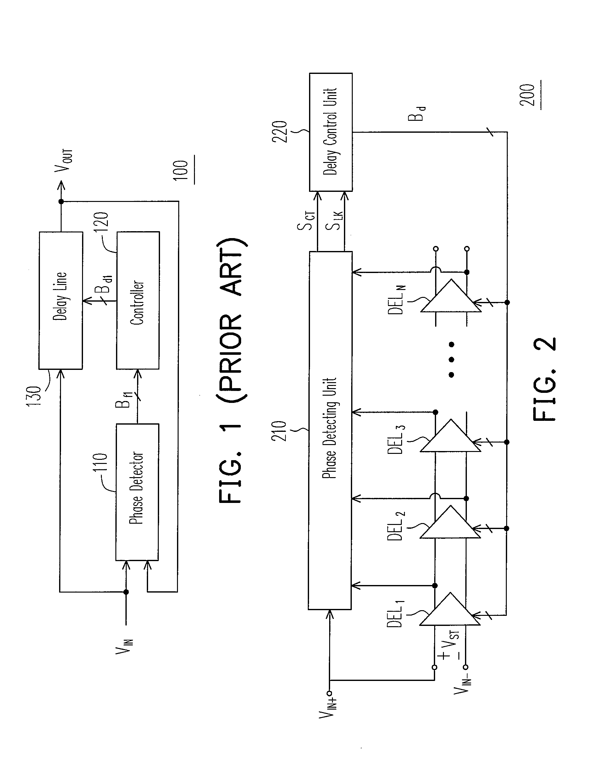
[0032]FIG. 2 is an architectural view of a digital phase locked loop according to an embodiment of the present invention. Referring to FIG. 2, a digital phase locked loop 200 includes a phase detecting unit 210, controllable delay circuits DEL1-DELN, and a delay control unit 220, where N is an integer greater than 0. The controllable delay circuits DEL1-DELN are connected in series, and output ends of the controllable delay circuits DEL1-DELN are coupled to the phase detecting unit 210. The delay control unit 220 is coupled to the phase detecting unit 210.

[0033]Referring to FIG. 2, the controllable delay circuits DEL1-DELN of this embodiment employs a double-ended design, so a specific period signal VST defined in this embodiment includes a positive received signal VIN+ and a negative received signal VIN. Here, the digital phase locked loop 200 is used to regulate the positive received signal VIN+ to a phase locked signal. It should be noted that the duty cycle of the specific perio...


PUM


Abstract

A digital delay locked loop including a plurality of controllable delay circuits connected in series, a phase detecting unit, and a delay control unit is disclosed. As an output end of each of the controllable delay circuits is coupled to the phase detecting unit, the phase detecting unit samples a positive received signal at the transition points of a specific period signal transmitted by each of the controllable delay circuits.

Description

CROSS-REFERENCE TO RELATED APPLICATION[0001]This application claims the priority benefit of Taiwan application serial no. 95147032, filed Dec. 15, 2006. All disclosure of the Taiwan application is incorporated herein by reference.BACKGROUND OF THE INVENTION[0002]1. Field of the Invention[0003]The present invention relates to a digital delay locked loop. More particularly, the present invention relates to a digital delay locked loop that detects phases according to a specific period signal transmitted by each of a plurality of controllable delay circuits.[0004]2. Description of Related Art[0005]Delay locked loops are mainly used for synchronizing and tracking of clock signals among different circuit systems. For example, in high-speed microprocessors, the delay locked loops are used to eliminate asynchronism between external clock signals and internal clock signals. In communication systems, the delay locked loops are used to recover clocks or data of the systems. Therefore, the dela...

Claims


Application Information

Patent Timeline
Patent Type & Authority Applications(United States)
IPC IPC(8): H03L7/08
CPCH03K5/1565H03K5/133H03L7/0814H03L7/0816
Inventor HUANG, HONG-YIJAN, SHIUN-DIANCHU, YUAN-HUA
Owner IND TECH RES INST
Why Eureka
Try Eureka