Method and apparatus for repairing a jet pump diffuser adapter to tailpipe weld

Active Publication Date: 2008-06-19
GENERAL ELECTRIC CO
View PDF35 Cites 24 Cited by
  • Summary
  • Abstract
  • Description
  • Claims
  • Application Information

AI Technical Summary

Benefits of technology

[0006]In an exemplary embodiment of the invention, a clamp assembly connects a diffuser adapter or lower ring to a diffuser tail pipe of a jet pump diffuser in a boiling water nuclear reactor. The clamp assembly includes at least two clamp segments shaped generally corresponding to an exterior circumference of the diffuser, a swivel link affixed at each end of each of the clamp segments, and at least two connecting bands pivotably secured to the swivel links between the ends of the clamp segments. The clamp segments each includes a locking assembly engageable with the diffuser adapter or lower ring and the diffuser tail pipe.
[0007]In another exemplary embodiment of the invention, a method of repairing a weld joining a diffuser adapter or lower ring to a diffu

Problems solved by technology

These two rings were shop-welded, as this was a bimetallic weld (a weld of diss

Method used


Image

  • Method and apparatus for repairing a jet pump diffuser adapter to tailpipe weld
  • Method and apparatus for repairing a jet pump diffuser adapter to tailpipe weld
  • Method and apparatus for repairing a jet pump diffuser adapter to tailpipe weld

Examples


Embodiment Construction

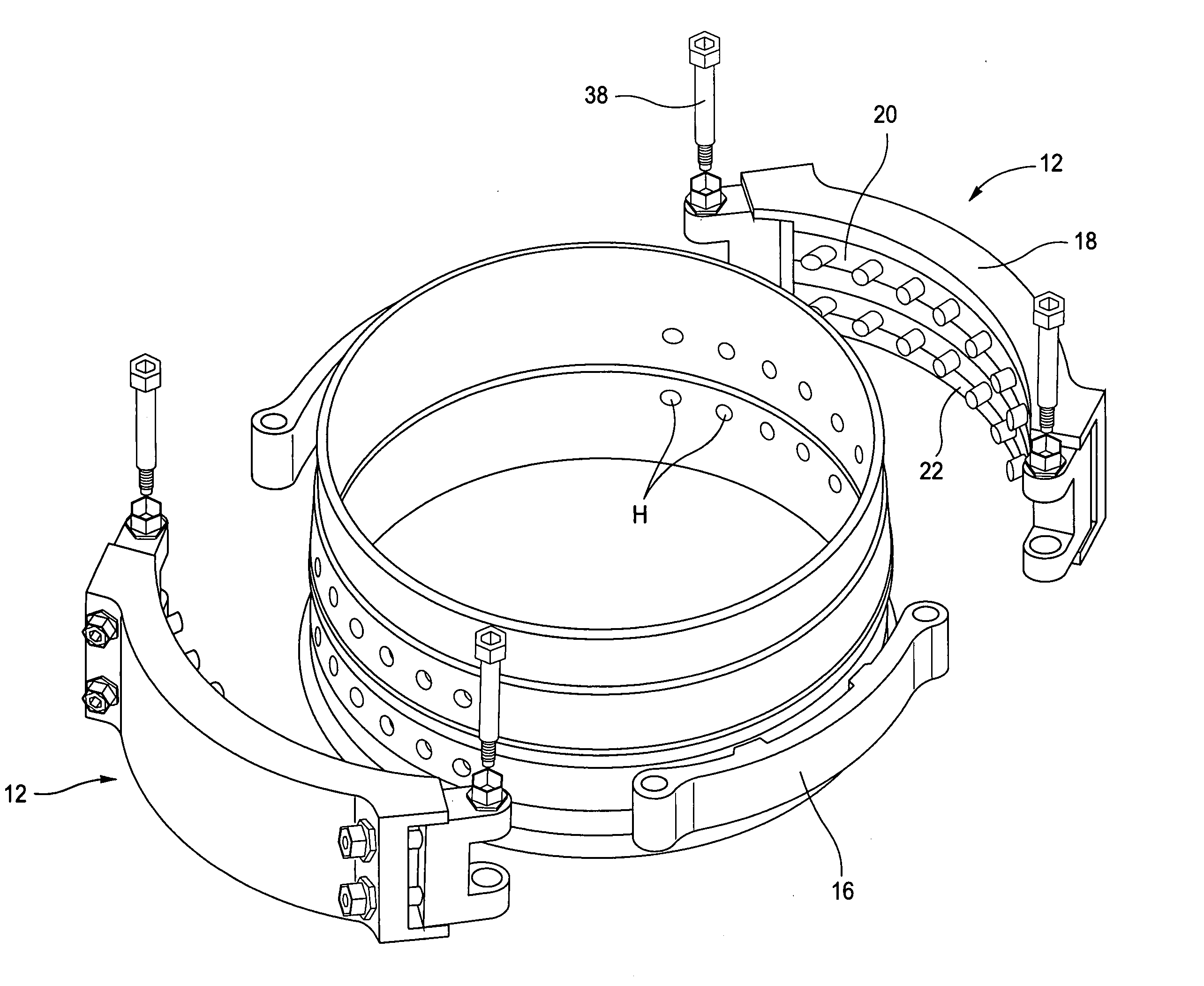
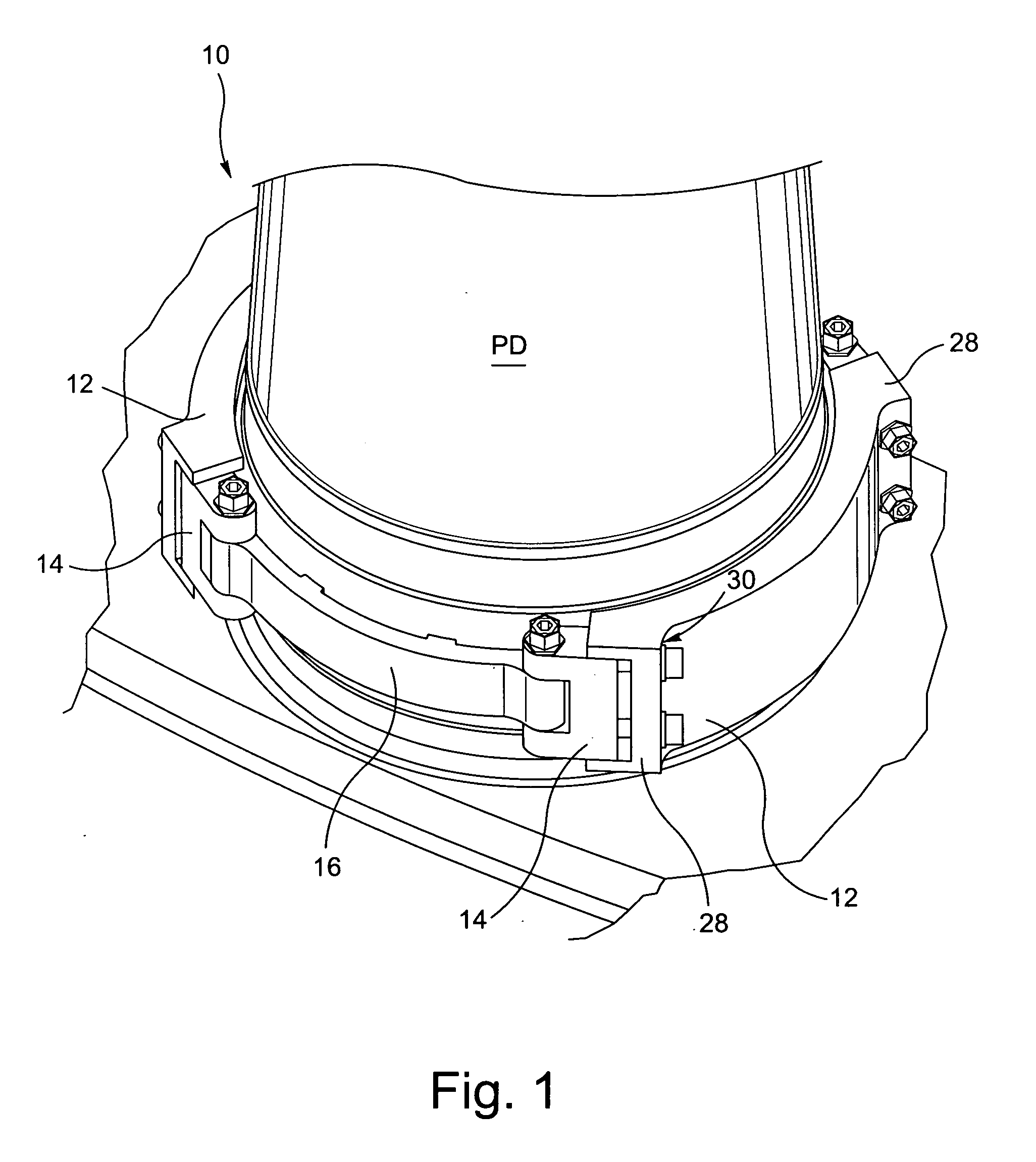
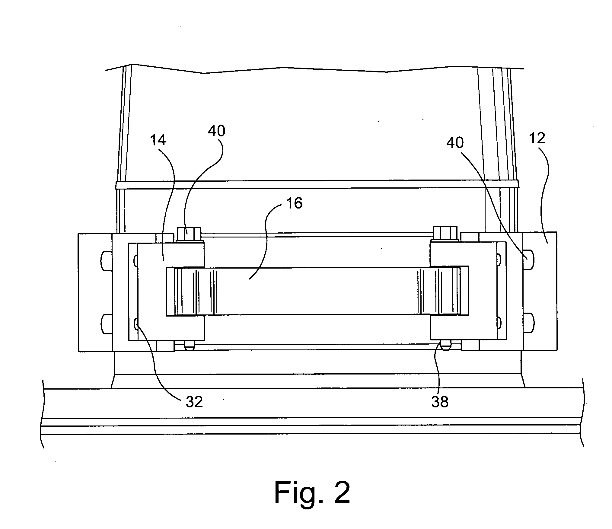
[0016]The jet pump diffuser clamp assembly 10 is shown installed on a jet pump diffuser PD in FIGS. 1-3. Components of the clamp assembly 10 include clamp segments 12 shaped generally corresponding to an exterior circumference of the diffuser PD, swivel links 14 affixed at each end of the clamp segments 12, and connecting bands 16 pivotably secured to the swivel links 14 between the ends of the clamp segments 12.

[0017]As shown in FIGS. 4, 6 and 7, the clamp segments 12 are comprised of a clamp body 18 and a pair of pin inserts, including an upper pin insert 20 and a lower pin insert 22. The clamp bodies 18 each include a pair of circumferential channels 24 on an inside surface thereof that are sized to receive the upper and lower pin inserts 20, 22. The pin inserts 20, 22 include a plurality of pins 26 engageable with corresponding holes H formed in the diffuser adapter or lower ring DA and the diffuser tailpipe TP. Preferably, the pins 26 are conically shaped, and the holes H forme...


PUM

PropertyMeasurementUnit
Circumferenceaaaaaaaaaa
Distributionaaaaaaaaaa
Coefficient of linear thermal expansionaaaaaaaaaa

Abstract

A clamp assembly connects a diffuser adapter or lower ring to a diffuser tail pipe of a jet pump diffuser in a boiling water nuclear reactor. The clamp assembly includes at least two clamp segments shaped generally corresponding to an exterior circumference of the diffuser, a swivel link affixed at each end of each of the clamp segments, and at least two connecting bands pivotably secured to the swivel links between the ends of the clamp segments. The clamp segments each includes a locking assembly engageable with the diffuser adapter or lower ring and the diffuser tail pipe. The clamp assembly structurally replaces/repairs the weld joining the diffuser adapter or lower ring and the diffuser tail pipe.

Description

BACKGROUND OF THE INVENTION[0001]The invention relates to repairing or replacing a bimetallic weld in a jetpump diffuser assembly and, more particularly, to a jet pump diffuser clamping assembly that structurally replaces / repairs the weld.[0002]In a boiling water nuclear reactor, hollow tubular jet pumps positioned within the shroud annulus provide the required reactor core flow. The lower portion of the jet pump is a long conical tubular section. The function of the diffuser is to slow the high velocity flow stream and thus convert the dynamic head of the flow stream into static pressure.[0003]The jet pump diffuser assemblies in boiling water reactors can be one of two differing design configurations. The first configuration incorporates an adapter component, which is comprised of an upper austenitic stainless steel ring and a lower inconel alloy 600 ring. These two rings were shop-welded, as this was a bimetallic weld (a weld of dissimilar metals) and more difficult to perform tha...

Claims


Application Information

Patent Timeline
IPC IPC(8): G21C19/28
CPCG21C19/02G21C19/207G21Y2004/501G21Y2002/401G21Y2004/40G21Y2002/301Y02E30/30
Inventor JENSEN, GRANT C.BOURBOUR, SIAMAK
Owner GENERAL ELECTRIC CO
Why Eureka
Try Eureka