Image Forming Apparatus
- Summary
- Abstract
- Description
- Claims
- Application Information
AI Technical Summary
Benefits of technology
Problems solved by technology
Method used
Image

Examples
first embodiment
[0077]An exemplary printing process according to the present invention is described below with reference to FIGS. 9A, 9B, and 10.
[0078]First, an exemplary process of consecutively printing multiple pages is described with reference to FIGS. 9A and 9B. FIGS. 9A and 9B illustrate a process of printing multiple pages where the leading edge of a succeeding paper sheet is detected after the printing on a preceding paper sheet is completed.
[0079]As shown in FIG. 9A, when the scanning of a preceding paper sheet 12a is finished, a succeeding paper sheet 12b is conveyed with a certain distance from the preceding paper sheet 12 as described above.
[0080]As shown in FIG. 9B, the carriage 3 moves in the direction shown by the arrow to a paper edge detection position (a predetermined position where the leading edge of the paper sheet 12 is detected) to detect the leading edge of the succeeding paper sheet 12b. To improve the productivity (or printing speed), the succeeding paper sheet 12b is conv...
second embodiment
[0086]An exemplary printing process according to the present invention is described below with reference to FIGS. 11 and 12.
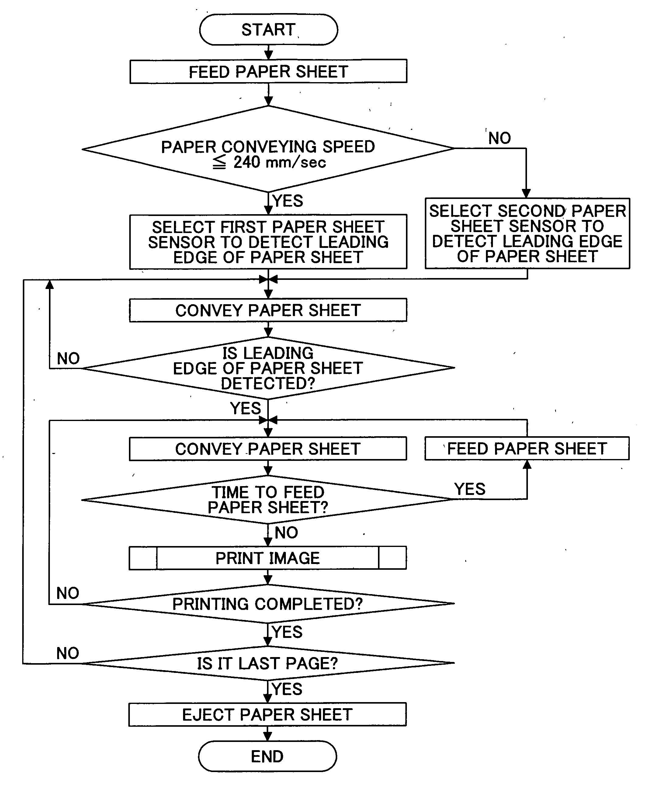
[0087]According to the second embodiment, the control unit 100 selects either the first paper sheet sensor 81 or the second paper sheet sensor 82 to detect the leading edge of the paper sheet 12 according to a print property. In this embodiment, the distance between paper sheets is changed according to a print property (paper type, in this example) as shown in FIG. 12. As shown in FIG. 12, the distance between paper sheets is set to a small value (for example, 40 mm) for plain paper, because a higher printing speed is demanded when printing on plain paper. On the other hand, the distance between gloss paper sheets or OHP sheets is set to a larger value (for example, 60 mm), because a smaller value increases the risk of causing paper feed troubles.
[0088]When the paper conveying speed is constant, the time from when the final scanning of a preceding paper sheet i...
third embodiment
[0096]An exemplary printing process according to the present invention is described below with reference to FIGS. 13 through 15.
[0097]In the third embodiment, the first paper sheet sensor 81 works in conjunction with the second paper sheet sensor 82. In the exemplary printing process shown in FIG. 13, the control unit 100 causes the paper feed roller 13 to feed the paper sheet 12, causes the conveyor belt 21 to convey the paper sheet 12, and detects the leading edge of the paper sheet 12 using the second paper sheet sensor 82. The control unit 100 stores the timing (the number of pulses) at which the second paper sheet sensor 82 has detected the leading edge of the paper sheet 12 or the distance obtained from the number of pulses and the paper conveying speed in a certain area in the RAM 103.
[0098]The CPU 101 in the control unit 100 compares condition data in the ROM 102, the RAM 103, and the non-volatile memory 104 with the paper detection timing data stored in the RAM 103 and ther...
PUM
 Abstract
Description
Claims
Application Information
 - Generate Ideas
- Intellectual Property
- Life Sciences
- Materials
- Tech Scout
- Unparalleled Data Quality
- Higher Quality Content
- 60% Fewer Hallucinations
Browse by: Latest US Patents, China's latest patents, Technical Efficacy Thesaurus, Application Domain, Technology Topic, Popular Technical Reports.
© 2025 PatSnap. All rights reserved.Legal|Privacy policy|Modern Slavery Act Transparency Statement|Sitemap|About US| Contact US: help@patsnap.com