Controlling uplink power for picocell communications within a macrocell

a macrocell and uplink power technology, applied in the field of communication, can solve the problems of macrocell base stations suffering from interference, picocells suffering from interference,

Inactive Publication Date: 2008-06-19
LUCENT TECH INC
View PDF21 Cites 211 Cited by
  • Summary
  • Abstract
  • Description
  • Claims
  • Application Information

AI Technical Summary

Problems solved by technology

Various challenges are introduced by the possibility of having one or more picocell base station units within a macrocell.
These challenges become even more complex with the potential proliferation of hundreds or even thousands of picocells within a macrocell.
For example, there can be mutual, co-channel interference between a picocell base station unit and a macrocell base station.
In an uplink direction, the picocell suffers from interference when a macrocell mobile station is nearby and transmitting on an uplink.
On the other hand, macrocell base stations suffer from interference when ...

Method used


Image

  • Controlling uplink power for picocell communications within a macrocell
  • Controlling uplink power for picocell communications within a macrocell
  • Controlling uplink power for picocell communications within a macrocell

Examples


Embodiment Construction

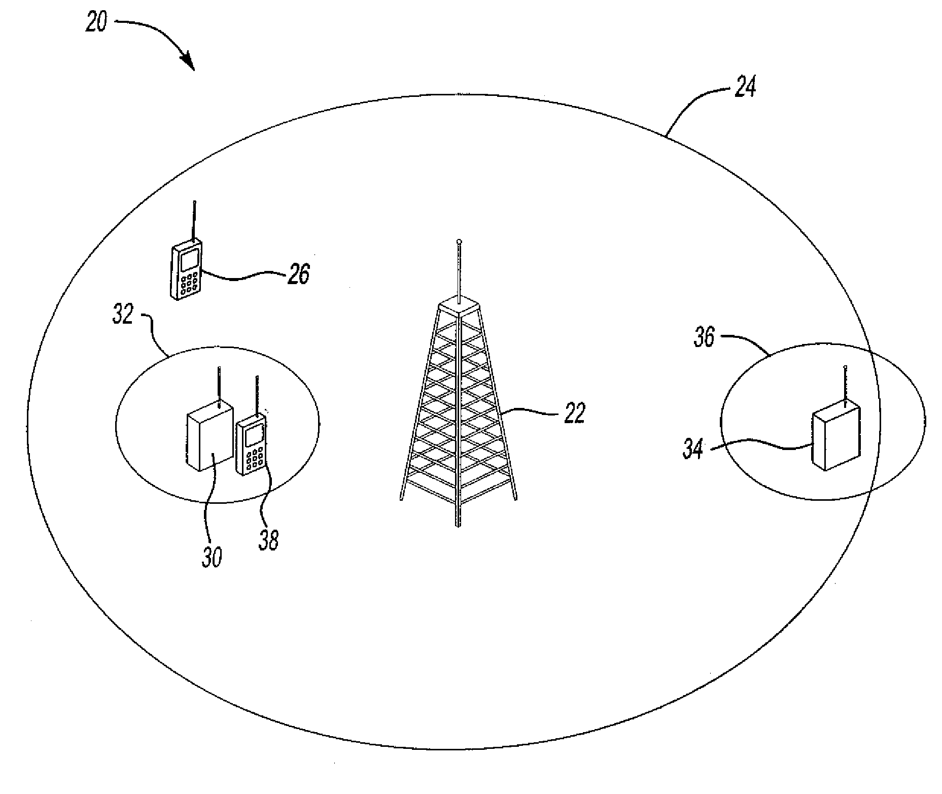
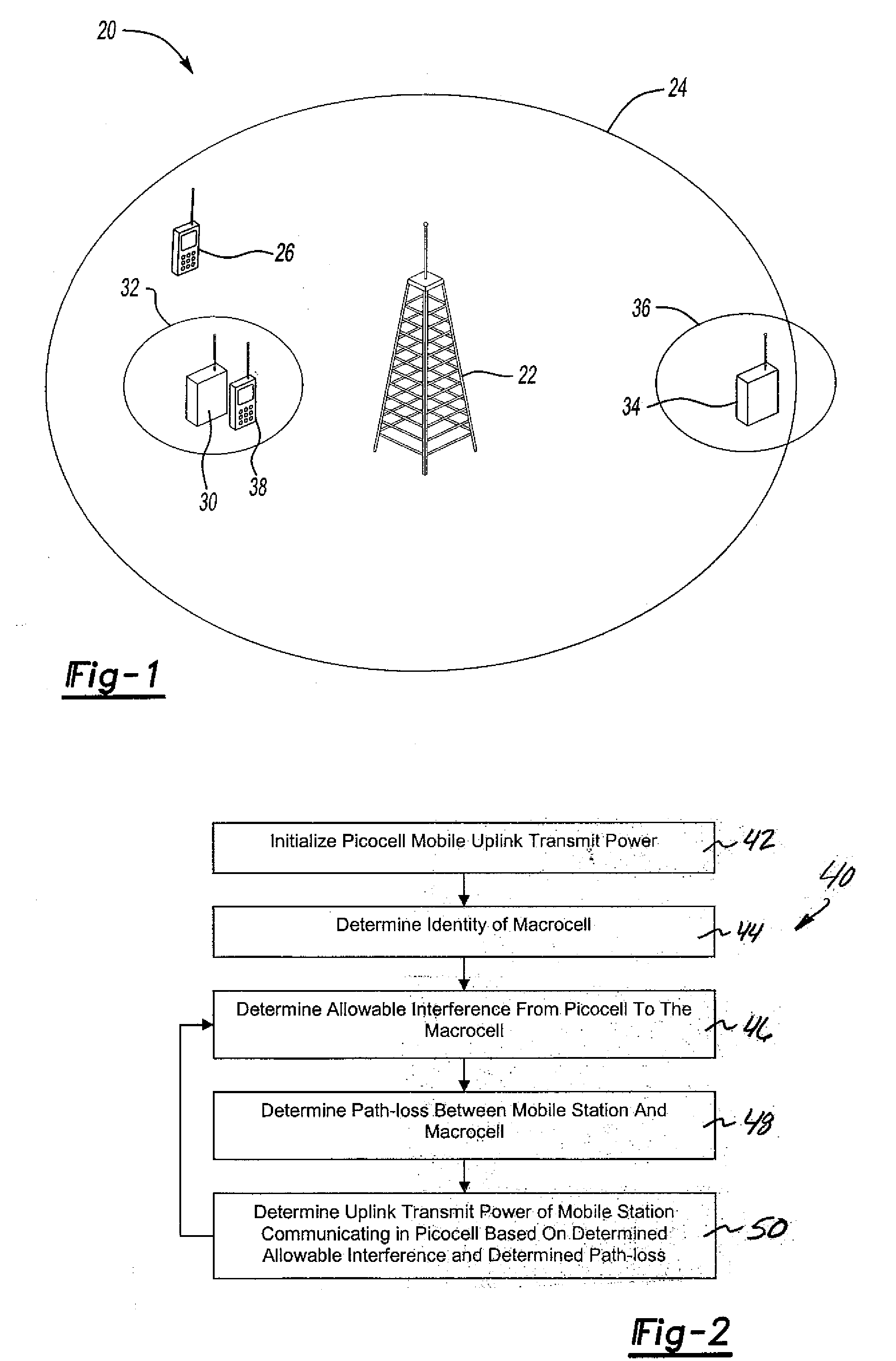
[0012]Disclosed example techniques provide for dynamically adjusting an uplink transmit power of a mobile station communicating in a picocell within a macrocell. Disclosed examples guarantee a controlled amount of interference at the macrocell base station while providing for a reliable, adjustable transmit power for communications within a picocell.

[0013]FIG. 1 schematically illustrates selected portions of a communication system 20. A base station 22 includes a base station transceiver unit and appropriate radio communication equipment for conducting wireless communications in a generally known manner. The base station 22 establishes a wireless communication coverage area 24 that is referred to as a macrocell for purposes of discussion. The geographic region of the macrocell 24 will depend, in part, on the capabilities of the base station 22 and the surrounding geography. There are known techniques for establishing a desired macrocell coverage area.

[0014]Within the macrocell 24 a ...


PUM


Abstract

A method of communicating in a picocell within a macrocell includes automatically setting an uplink transmit power of a mobile station to avoid uplink interference between the picocell and the macrocell. A disclosed example includes determining an allowable interference from the picocell to the macrocell. A path-loss between a mobile station and a macrocell is determined. An uplink transmit power of the mobile station for communicating in the picocell is determined based upon the determined allowable interference and the determined path-loss.

Description

1. TECHNICAL FIELD[0001]This invention generally relates to communication. More particularly, this invention relates to wireless communication.2. DESCRIPTION OF THE RELATED ART[0002]Wireless communication systems are well known and in widespread use. Many systems are referred to as cellular systems because of the way that wireless communication coverage is designed. Base station transceivers are arranged to provide wireless communication coverage over geographic areas surrounding the base station. The geographic area is typically referred to as a cell. The typical relatively large size or coverage area of such cells allows for them to be referred to as macrocells.[0003]It is possible to establish smaller-sized cells within a macrocell. These are sometimes referred to as picocells. One proposed way for establishing a picocell is to provide a home base station unit or picocell base station unit that operates within a relatively limited range such as within a building, for example.[000...

Claims


Application Information

Patent Timeline
IPC IPC(8): H04Q7/20H04B1/00H04B15/00H04W16/32H04W52/14
CPCH04W16/32H04W52/367H04W52/244H04W52/146H04W52/24H04W52/26
Inventor CLAUSSEN, HOLGERWEE HO, LESTER TSESAMUEL, LOUIS GWYN
Owner LUCENT TECH INC
Why Eureka
Try Eureka