

Electrical conductive roller and imaging apparatus comprising the same
a technology of electrical conductive rollers and imaging apparatuses, which is applied in the direction of cleaning processes, instruments, shafts and bearings, etc., can solve the problems of long drying lines, long drying time for the formation of resin coating layers, and quality problems, so as to improve durability, stably form good images, and improve durability.
Inactive Publication Date: 2008-06-19
BRIDGESTONE CORP
View PDF4 Cites 45 Cited by
- Summary
- Abstract
- Description
- Claims
- Application Information
AI Technical Summary
Benefits of technology
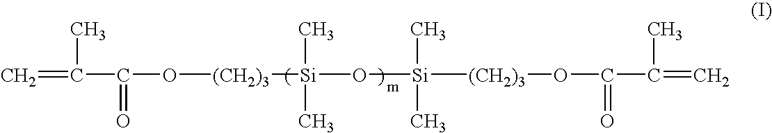
[0021]According to the invention, in the electrical conductive roller provided on the surface of the elastic layer with the resin coating layer, there can be provided an electrical conductive roller improving the durability to the chipping of the resin coating layer by using as the resin coating layer the ultraviolet-cured resin, which is formed by curing the paint mixture of (metha)acrylate oligomer (A), (metha)acrylate monomer (B) and photopolymerization initiator (C) through irradiation of ultraviolet ray
Problems solved by technology
At this moment, the drying for the formation of the resin coating layer is required to take a long time, and hence a long drying line is required in the mass production thereof.
Also, the resin coating layer is required to have delicate electrical conductivity and surface state for its applications, but the scattering of temperature distribution, air volume and the like in the drying line largely exerts on the performances of the resin coating layer, so that there is a problem in the quality thereof.
However, the resin coating layer formed by curing the ult
Method used
View moreImage
Smart ImageViewing Examples

Examples
 PUM
 Abstract
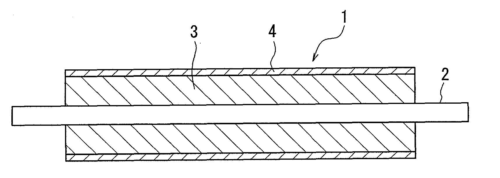
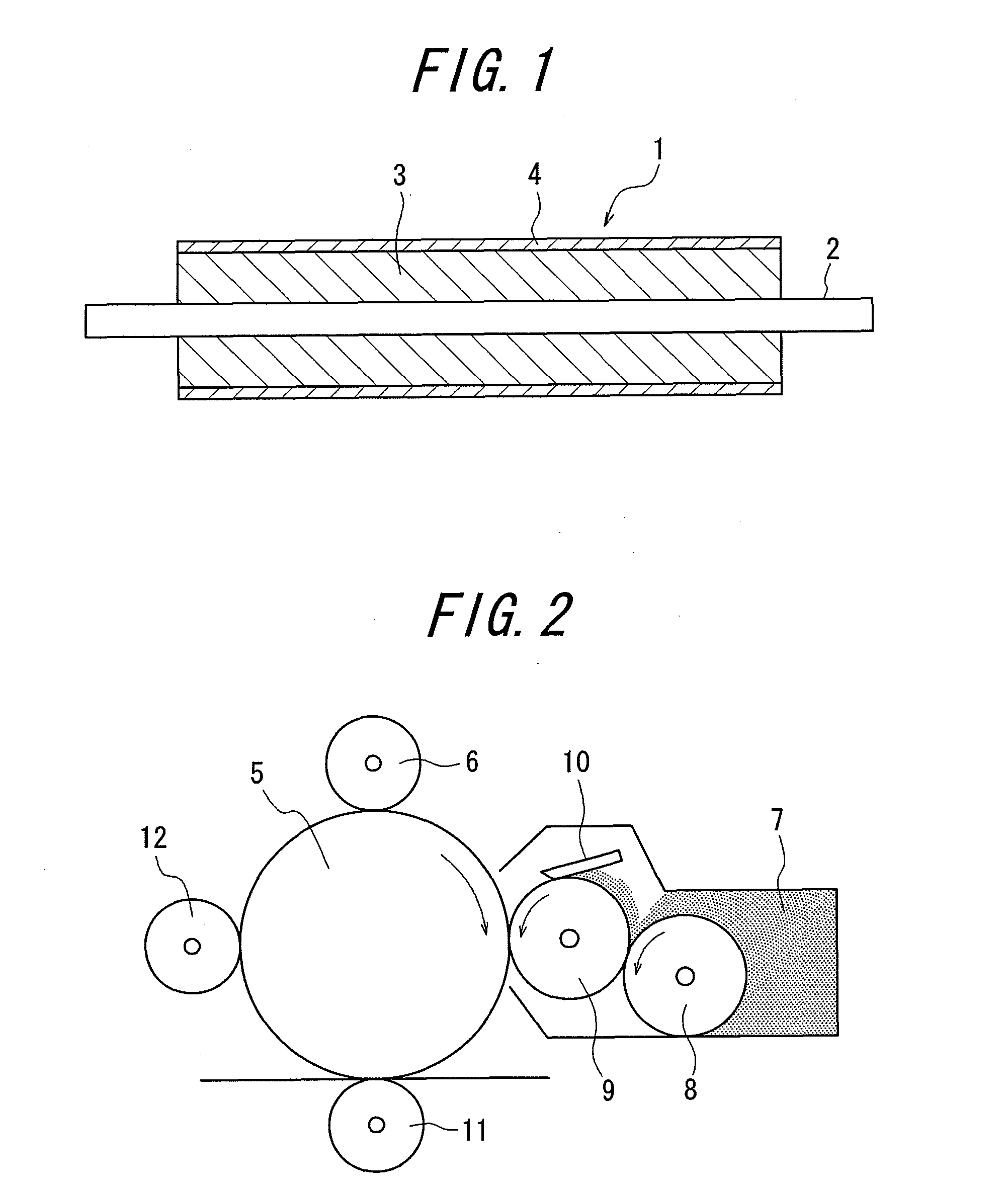
An electrical conductive roller comprises a shaft member, an elastic layer disposed on an outer side of the shaft member in a radial direction and at least one resin coating layer disposed on an outer side of the elastic layer in the radial direction, wherein a resin coating layer at least adjacent to the elastic layer is made of a ultraviolet-cured resin formed by curing a paint for the resin coating layer comprising (A) a (metha)acrylate oligomer, (B) a (metha)acrylate monomer and (C) a photopolymerization initiator through irradiation of ultraviolet rays, and having an elongation at break of not less than 80%.
Description
BACKGROUND OF THE INVENTION[0001]1. Field of the Invention[0002]This invention relates to an electrical conductive roller comprising an elastic layer and a resin coating layer and an imaging apparatus comprising such an electrical conductive roller, and more particularly to an electrical conductive roller having an improved durability and an imaging apparatus comprising such an electrical conductive roller and capable of forming good images.[0003]2. Description of the Related Art[0004]In general, a roll-shaped electrically conductive elastic member, i.e. an electrical conductive roller is frequently used as a developing roller, a charge roller, a toner feed roller, a transfer roller, a paper feed roller, a cleaning roller, a pressing fuser roller or the like in an imaging apparatus of an electrophotographic system such as a copier, a facsimile, a laser beam printer (LBP) or the like. The electrical conductive roller usually comprises a shaft member attached so as to bear both end po...
Claims
Login to View More Application Information
Patent Timeline
 IPC IPC(8): F16C13/00
CPCG03G15/0233G03G21/0058G03G15/1685G03G15/0818B08B7/0028
InventorOSAKU, AKIHIDE
OwnerBRIDGESTONE CORP