Marking registers as available for register renaming

a register and register technology, applied in the field of data processing, can solve problems such as exasperation, difficulty in avoiding write after read (war) hazards, and inability to execute renaming circuits

Inactive Publication Date: 2008-06-19
ARM LTD
View PDF13 Cites 43 Cited by
  • Summary
  • Abstract
  • Description
  • Claims
  • Application Information

AI Technical Summary

Benefits of technology

[0012]Furthermore, it is the register renaming logic itself that performs the step of marking the registers as available thus, it can be performed quickly and power efficiently.
[0020]To increase security further all registers not in the recovery file can be reset by overwriting them with a dummy value. This is a robust defence against any security breach.
[0022]In some embodiments, it may be advantageous to be able to turn the present technique on and off. For example, at times it may not be needed, whereas at other times perhaps because of a bug or because of the design of the processor it may be needed. The ability to turn the technique on and off allows the continual monitoring for predetermined conditions to be turned off and power saved when the technique is not needed.
[0024]An alternative to having a switch value, or in some cases potentially an addition is to set the system so that it can deal with there being no physical registers available any more. Thus, if it occurs that there are no further physical registers available, the present technique simply stalls renaming until processing of any pending instructions downstream of the renaming stage that produce registers have produced them. At this point, it is recognised that only those registers renamed in the recovery file are required and all other registers are available. Thus, the system can simply mark all the other registers as available and can continue processing.

Problems solved by technology

This can cause problems if the data used by these instructions is stored in a very limited register set as a value stored in one register may be overwritten before it is used by another instruction.
This leads to errors.
This can lead to potential problems in that an instruction which has been through the renaming circuitry may not execute, as it may abort or it may be on a wrongly predicted branch.
A further issue with renaming is that when an architectural register is to be mapped to a physical register it is necessary to identify which of the physical registers are available to be used for such a mapping.
However, avoiding write after read (WAR) hazards is more difficult.
Furthermore, this problem is exasperated when instructions do not complete following renaming.
In such a case it is difficult to know when a physical register that has been used to map an architectural one is not required any more for that instruction and is therefore available for mapping by another architectural register.
This problem is exasperated by the ARM instruction set having conditional instructions, resulting in more instructions being renamed and then not successfully executing than would be the case without conditional instructions.
One example where this problem may occur is in a multiple load operable to load a number of registers which aborts halfway through and thus does not complete.
Failure to do this results in a register being lost to the processor.
For this reason the process of marking as available registers that have been renamed but the instruction has not executed was conventionally an exact process and was expensive in either processing time or hardware.

Method used


Image

  • Marking registers as available for register renaming
  • Marking registers as available for register renaming
  • Marking registers as available for register renaming

Examples


Embodiment Construction

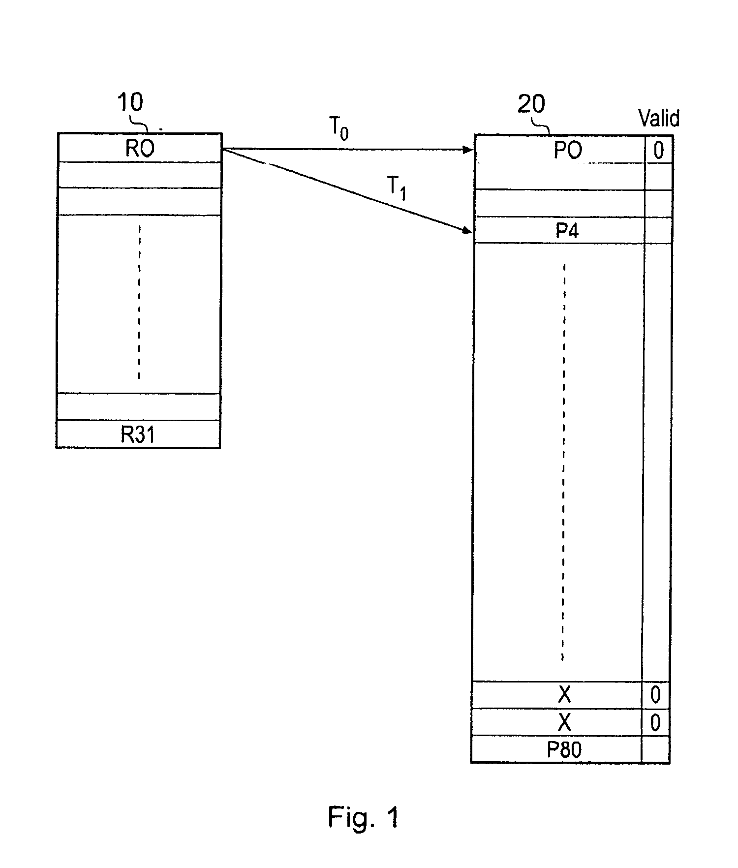
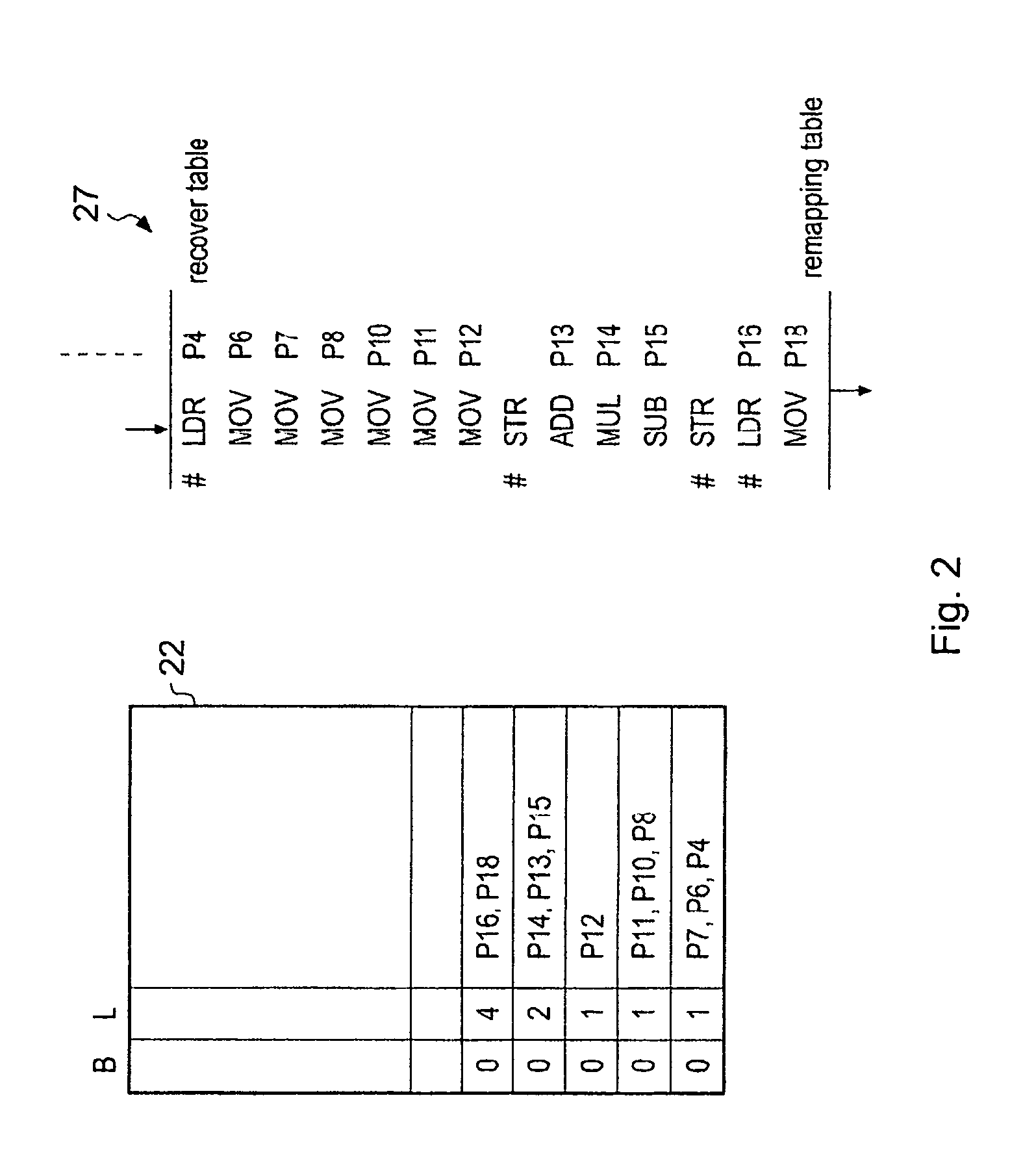
[0045]FIG. 1 schematically shows a set of architectural registers R0 to R31 being mapped to a set of physical registers P0 to P80. In register renaming a single architectural register can be mapped onto multiple physical registers, each physical register being a different view in time of this architectural register. This is shown by register R0 being mapped to register P0 at time T0 and mapped to register P4 at time T1. These different mappings are stored in structures commonly called future files, the future files representing the different mapping architectural / physical registers with time. Each time a speculative block of instructions is known to be effectively committed the associated further file becomes the “recovery” file offering the latest known stable state of the system (This is illustrated in FIG. 2).

[0046]This ability to map an architecture register to more than one of the physical registers is one way of allowing out of order processing of the instructions to be suppor...


PUM


Abstract

The present application discloses register renaming circuitry for mapping registers from an architectural set of registers to registers within a physical set of registers, said architectural set of registers being registers specified by instructions within an instruction set and said physical set of registers being registers within a processor for processing instructions of said instruction set, said instruction set comprising exception instructions and non-exception instructions, exception instructions being instructions that may generate an exception and non-exception instructions being instructions that execute in a statically determinable way, said register renaming circuitry comprising: a first data store for storing a future renaming table, said future renaming table comprising renaming values for mapping registers from said architectural set of registers to registers in said physical set of registers for instructions that are to be executed or are currently being executed by said processor; a second data store for storing a recovery renaming table, said recovery renaming table comprising a most recently committed mapping of said processor; wherein said register renaming circuitry is responsive to detection of a predetermined condition to mark said physical registers not mapped in said recovery renaming table as available for renaming.

Description

BACKGROUND OF THE INVENTION[0001]1. Field of the Invention[0002]The field of the invention relates to data processing and in particular to register renaming in a CPU.[0003]2. Description of the Prior Art[0004]It is known to provide processors which process instructions from an instruction set specifying an architectural set of registers using a physical set of registers that is larger than the architectural set. This is a technique that has been developed to try to avoid resource conflicts due to instructions executing out of order in the processor. In order to have compact instruction encodings most processor instruction sets have a small set of register locations that can be directly named. These are often referred to as the architecture registers and in many ARMS (registered trade mark of ARM Ltd Cambridge UK) RISC instruction sets there will be 32 architecture registers.[0005]When instructions are processed different instructions take different amounts of time. In order to speed...

Claims


Application Information

Patent Timeline
Patent Type & Authority Applications(United States)
IPC IPC(8): G06F15/00
CPCG06F9/384G06F9/3863G06F9/3842
Inventor PIRY, FREDERIC CLAUDE MARIEVINCENT, MELANIE EMANUELLE LUCIEBEGON, FLORENTGRANDOU, GILLES ERICLATAILLE, NORBERT BERNARD EUGENE
Owner ARM LTD
Why Eureka
Try Eureka