Error Correction Coding Apparatus and Error Correction Decoding Apparatus

a technology of error correction and coding apparatus, applied in the field of error correction coding and decoding technology, can solve problems such as the difficulty of selecting another factor among the factors of n, and achieve the effect of preventing the increase of the circuit scale and improving the correcting capability

Active Publication Date: 2008-06-19
MITSUBISHI ELECTRIC CORP
View PDF5 Cites 17 Cited by
  • Summary
  • Abstract
  • Description
  • Claims
  • Application Information

AI Technical Summary

Benefits of technology

[0009]Thus, the error correction coding / decoding apparatus in accordance with the present invention divides transmission information sequences in n subframes (n is an arbitrary natural number) into n1 subframes and n2 subframes (n1 and n2 are natural numbers which satisfy n1+n2=n) and then carries out the error correction coding. Therefore, because the error correction coding / decoding apparatus can select the bit number per one symbol of an error correction code freely from among numbers other than the factors of n, it can improve its correcting capability while preventing its circuit scale from increasing.

Problems solved by technology

However, there may be a case where it is difficult to select another factor from among the factors of n, considering the viewpoint of the circuit scale.

Method used


Image

  • Error Correction Coding Apparatus and Error Correction Decoding Apparatus
  • Error Correction Coding Apparatus and Error Correction Decoding Apparatus
  • Error Correction Coding Apparatus and Error Correction Decoding Apparatus

Examples


embodiment 1

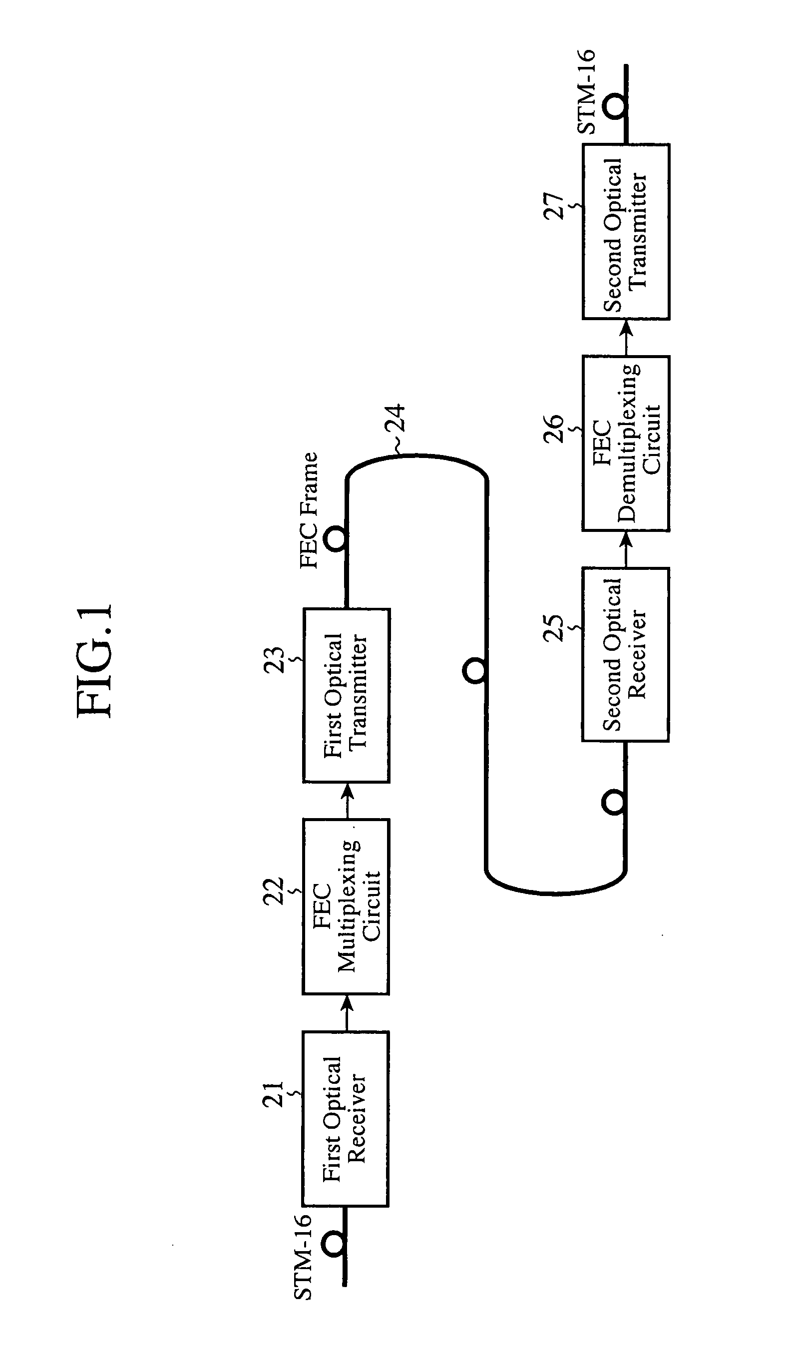
[0018]FIG. 1 is a block diagram showing the structure of an error correction coding system and that of an error correction decoding system in accordance with embodiment 1 of the present invention. The error correction coding and decoding systems shown in the figure transmit data at the same coding rate as that defined by the ITU-T recommendation G.975 on the basis of the frame format which complies with the ITU-T recommendation G. 709 generally used by optical communications. Conventionally, an error correction code is coded for every single FEC frame. In contrast, the error correction coding / decoding system shown is characterized in that it carries out error correction coding for every two or more FEC frames

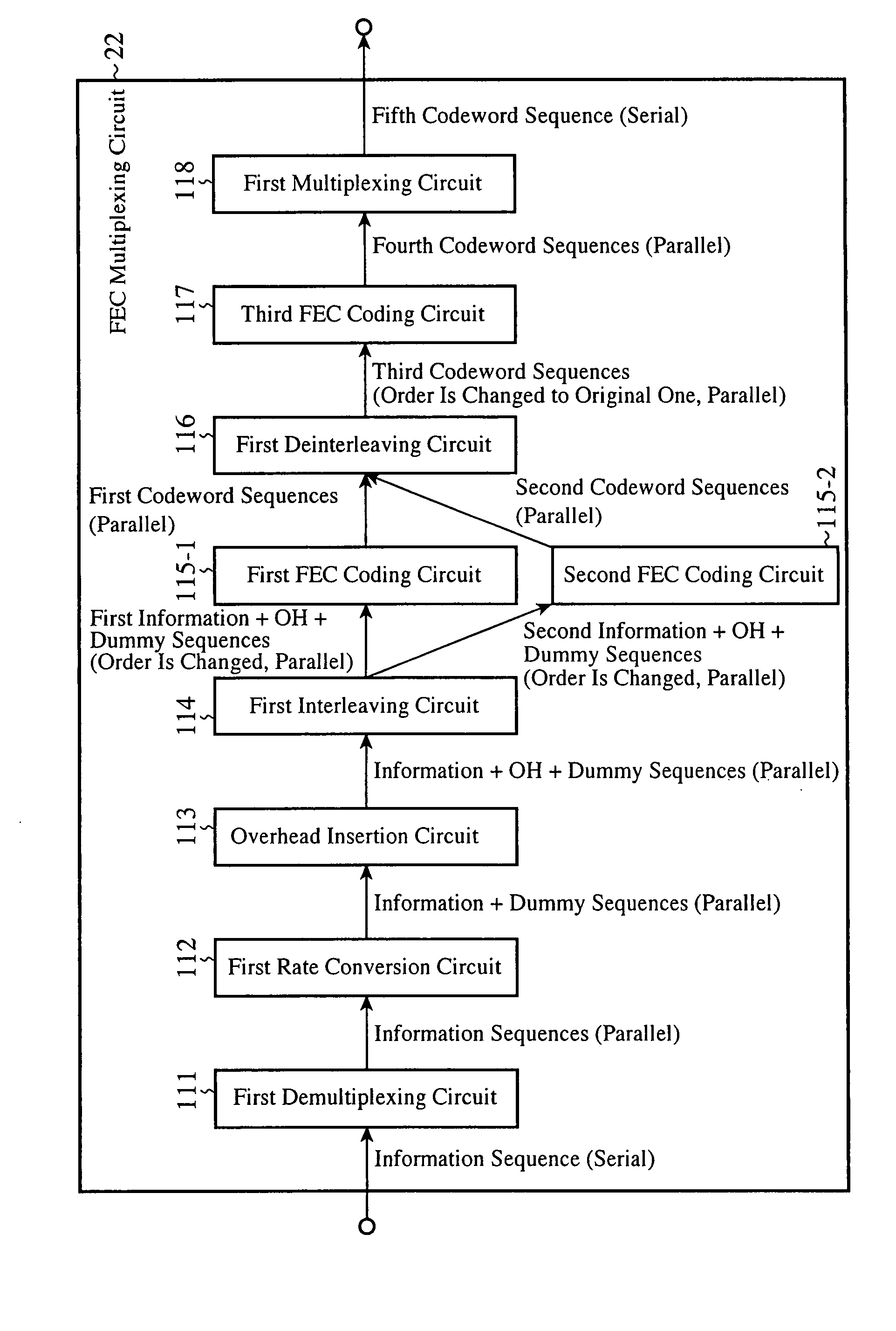
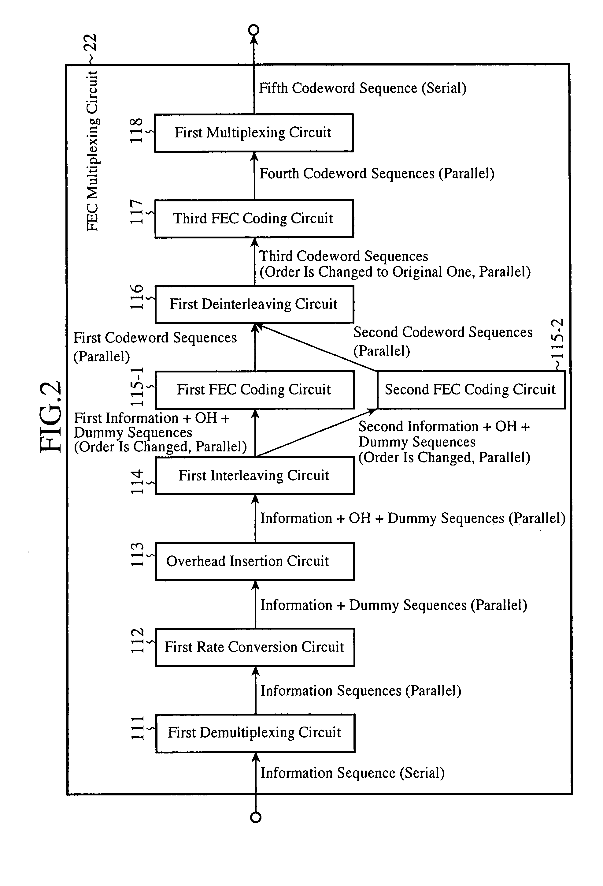
[0019]In FIG. 1, a first optical receiver 21 is a circuit which receives a optical signal, such as STM-16, STM-64, or STM-256, and converts the optical signal into an electric signal, and an FEC multiplexing circuit 22 is a circuit which demultiplexes the electric signal from th...

embodiment 2

[0081]In this embodiment 2 of the present invention, when a decoded result from a previous stage is delivered to a next stage decoding circuit in the error correction decoding process in accordance with embodiment 1 of the present invention, an error detection flag is set to a symbol of a non-binary code at a next stage containing a bit (referred to as an error detection bit from here on) corresponding to a codeword which was determined to be unable to be error-corrected at the time of the decoding circuit at the previous stage, and disappearance correction is carried out by the next stage decoding circuit using the error detection flag.

[0082]As an improvement of the above-mentioned method, there is provided a method of setting an error detection flag only when the number of error detection bits included in a symbol of a non-binary code is equal to or larger than a predetermined number b of bits. The setting of the error detection flag is done because the number of the same binary c...


PUM


Abstract

An error correction coding apparatus divides transmission information sequences in n subframes (n is an arbitrary natural number) into n1 subframes (n1 is a natural number<n) and n2 subframes (n2 is a natural number which satisfies n1+n2=n), block-codes the n1 subframes for every m1 subframes (m1 is a factor of n1) so as to generate a first error correction code, and block-codes the n2 subframes for every m2 subframes (m2 is a factor of n2) so as to generate a second error correction code.

Description

FIELD OF THE INVENTION[0001]The present invention relates to an error correction coding and decoding technology. More particularly, it relates to an error correction coding / decoding method using a block code, and an error correction coding / decoding apparatus which employs the method.BACKGROUND OF THE INVENTION[0002]According to a prior art FEC (Forward Error Correction), the number m of bits per one symbol of an error correction code is so set up as to be equal to a factor of the parallel number n of parallel sequences to be coded at the time of the error correction coding processing (for example, nonpatent reference 1).[0003]In general, according to such an FEC method, when the bit number m per one symbol of an error correction code is increased with the coding rate being fixed, the code length N can be lengthened and therefore the error correction capability can be improved. Therefore, in order to improve the error correction capability while a condition for selecting the bit numb...

Claims


Application Information

Patent Timeline
Patent Type & Authority Applications(United States)
IPC IPC(8): H03M13/00
CPCH03M13/134H03M13/2906H04L1/0083H04L1/0057H04L1/0064H04L1/0041
Inventor MIYATA, YOSHIKUNIYOSHIDA, HIDEOKUBO, KAZUO
Owner MITSUBISHI ELECTRIC CORP
Why Eureka
Try Eureka