Positioning device with a solid-body joint

a technology of solid-body joints and positioning devices, which is applied in the direction of piezoelectric/electrostrictive/magnetostrictive devices, instruments, electrical apparatuses, etc., can solve the problems of easy fracture of the actuator, and easy damage to the actuator, etc., to achieve the effect of easy fractur

Active Publication Date: 2008-06-26
ATTOCUBE SYST AG
View PDF4 Cites 17 Cited by
  • Summary
  • Abstract
  • Description
  • Claims
  • Application Information

AI Technical Summary

Benefits of technology

[0018]An especially advantageous configuration of the invention is characterized by the fact that the slip-stick drive has an actuator realized as a piezoelectric element. Piezoelectric elements are especially suitable for positioning devices having small increments (within the submicrometer range) and profit especially from the protection by the solid-body joint or joints, since they can easily fracture when subjected to torsional or shearing force.
[0019]A preferred realization of the positioning device according to the invention is characterized by the fact that the first unit is constructed in the form of a Ushaped housing having two legs and a base part connecting the legs, a solid-body joint or a plurality of solid-body joints extending between the housing legs. In this case, the actuator of the slip-stick drive can be expediently fixed to the base part of the housing. This realization of the positioning device according to the invention provides a robust construction of the positioning device, said construction being suitable for practical applications, in particular also under extreme conditions.

Problems solved by technology

Slip-stick drives are usually sensitive and can be easily damaged by shock.
In particular, the actuator which is often designed as a piezoelectric element can fracture or sustain damage in another way.
Experience shows that shock effects often occur on account of improper handling during assembly of the positioning device in the desired application or also during transport, e.g. by the positioning device falling to the ground.

Method used


Image

  • Positioning device with a solid-body joint
  • Positioning device with a solid-body joint
  • Positioning device with a solid-body joint

Examples


Embodiment Construction

[0027]Reference will now be made in detail to the embodiments, examples of which are illustrated in the accompanying drawings, wherein like reference numerals refer to the like elements throughout. The embodiments are described below to explain the present invention by referring to the figures.

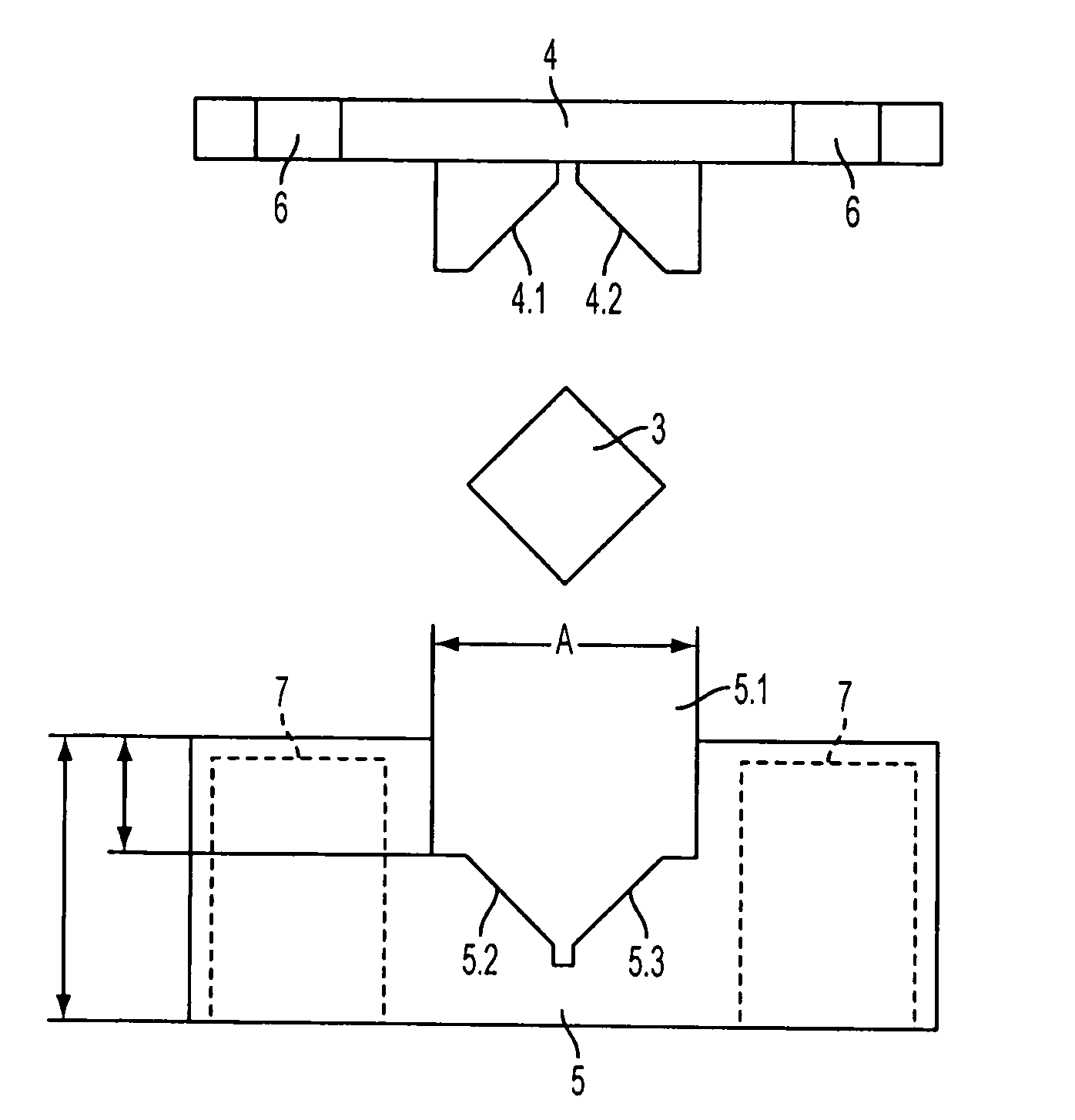
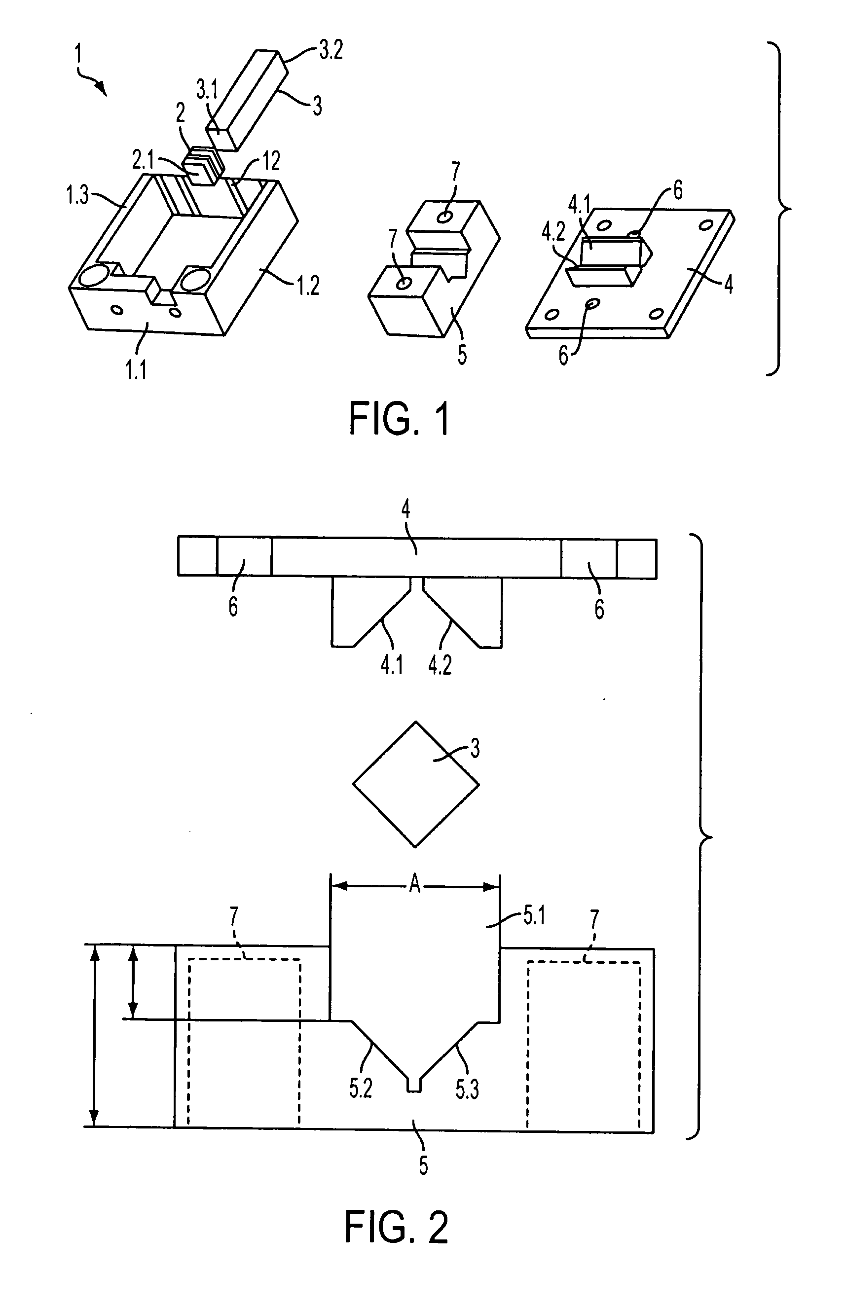
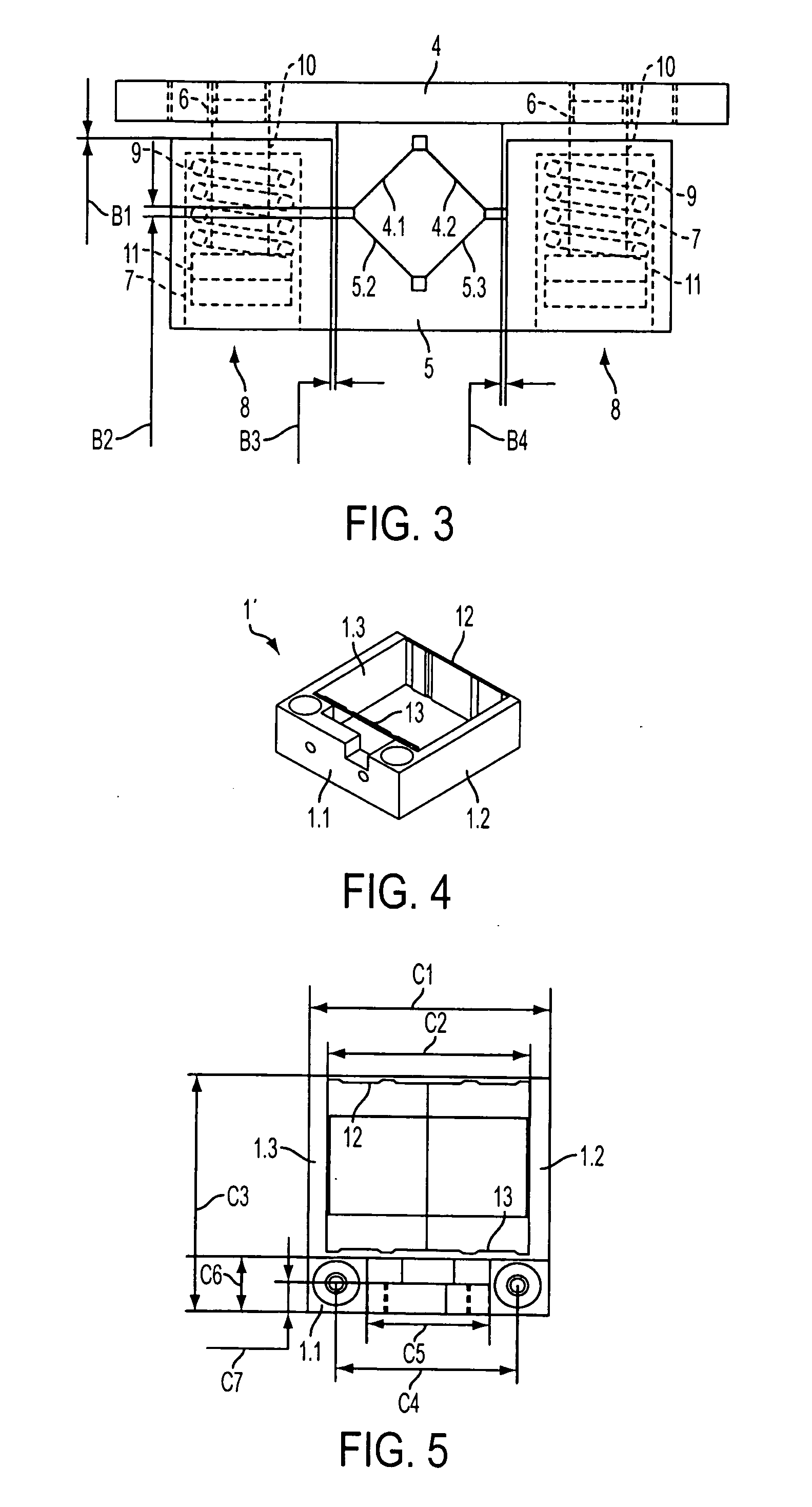
[0028]The positioning device 1 shown in FIG. 1 has a Ushaped housing 1, a piezoelectric element 2, a translation shaft 3, a support 4 and a support counterelement 5 designed like a shoe. The housing 1 is composed of a transverse profile 1.1 and two legs 1.2, 1.3 arranged perpendicularly to the transverse profile 1.1 on its ends. Extending between the ends of the legs 1.2, 1.3 is a “solid-body joint”12, which is explained in more detail below in connection with FIGS. 4 to 6. In the assembled state (not shown in FIG. 1), the translation shaft 3 extends in parallel with and centrally between the two legs 1.2 and 1.3, the transverse profile side end 3.1 of the translation shaft 3 being connected t...


PUM


Abstract

A positioning device has a first unit and a second unit arranged so as to be displaceable relative to the first unit. A slip-stick drive acts between the first unit and the second unit to produce a translatory movement (P) of the two units. The positioning device has a solid-body joint which is coupled to the first unit and the slip-stick drive and which mechanically protects a translation shaft of the slip-stick drive against rotation and/or lateral displacement.

Description

CROSS REFERENCE TO RELATED APPLICATIONS[0001]This application is a continuing application, filed under 35 U.S.C. §111(a), of International Application PCT / DE2006 / 000867, filed May 19, 2006, it being further noted that priority is claimed and based upon German Patent Application 10 2005 026 708.4, filed on Jun. 9, 2005, the disclosures of which are incorporated herein by reference.BACKGROUND[0002]1. Field[0003]The invention relates to a positioning device which in particular has a positioning accuracy within the submillimeter range.[0004]Positioning devices having positioning accuracies within the submillimeter range are used in a multiplicity of applications in research and industry. To achieve a high positioning accuracy, systems having as few mechanical parts as possible and having a high quality of the surfaces in the region of mechanical guides and engagements must be used. In addition to as high a reproducibility and scalability of paths of movement as possible, properties such...

Claims


Application Information

Patent Timeline
Patent Type & Authority Applications(United States)
IPC IPC(8): G01D21/00
CPCB23Q2210/002H02N2/025
Inventor HAFT, DIRKLINDENBERG, TOBIASBOEDEFELD, CHRISTOPH
Owner ATTOCUBE SYST AG
Why Eureka
Try Eureka