Control apparatus and control method for vehicular drive system

a control apparatus and control method technology, applied in the direction of engine-driven generators, propulsion parts, electric devices, etc., can solve the problems of inability to balance power, inability to control the speed of the first electric motor, and restricted output of the second electric motor

Inactive Publication Date: 2008-06-26
TOYOTA JIDOSHA KK
View PDF9 Cites 110 Cited by
  • Summary
  • Abstract
  • Description
  • Claims
  • Application Information

AI Technical Summary

Benefits of technology

[0015]This invention thus provides a control apparatus and a control method for a vehicular drive system, which can appropriately control the rotation speed of the first electric motor during a shift in a shifti

Problems solved by technology

As a result, the output of the second electric motor may be restricted to within that possible output range.
Therefore, when there are restrictions placed on charging/discharging of the power storage device and the output of the second electric motor, power is not able to be balanced.
As a result, the rotation speed of the first electric motor may not be able to be controlled appropriately when a shift is performed in the shifting portion, which may increase shift shock.
However, if the inertia effect during that shift is greater than the drag from the engine itself, the engine speed may enter the negative rotation speed rang

Method used


Image

  • Control apparatus and control method for vehicular drive system
  • Control apparatus and control method for vehicular drive system
  • Control apparatus and control method for vehicular drive system

Examples


Embodiment Construction

[0053]In the following description and the accompanying drawings, the present invention will be described in more detail in terms of example embodiments.

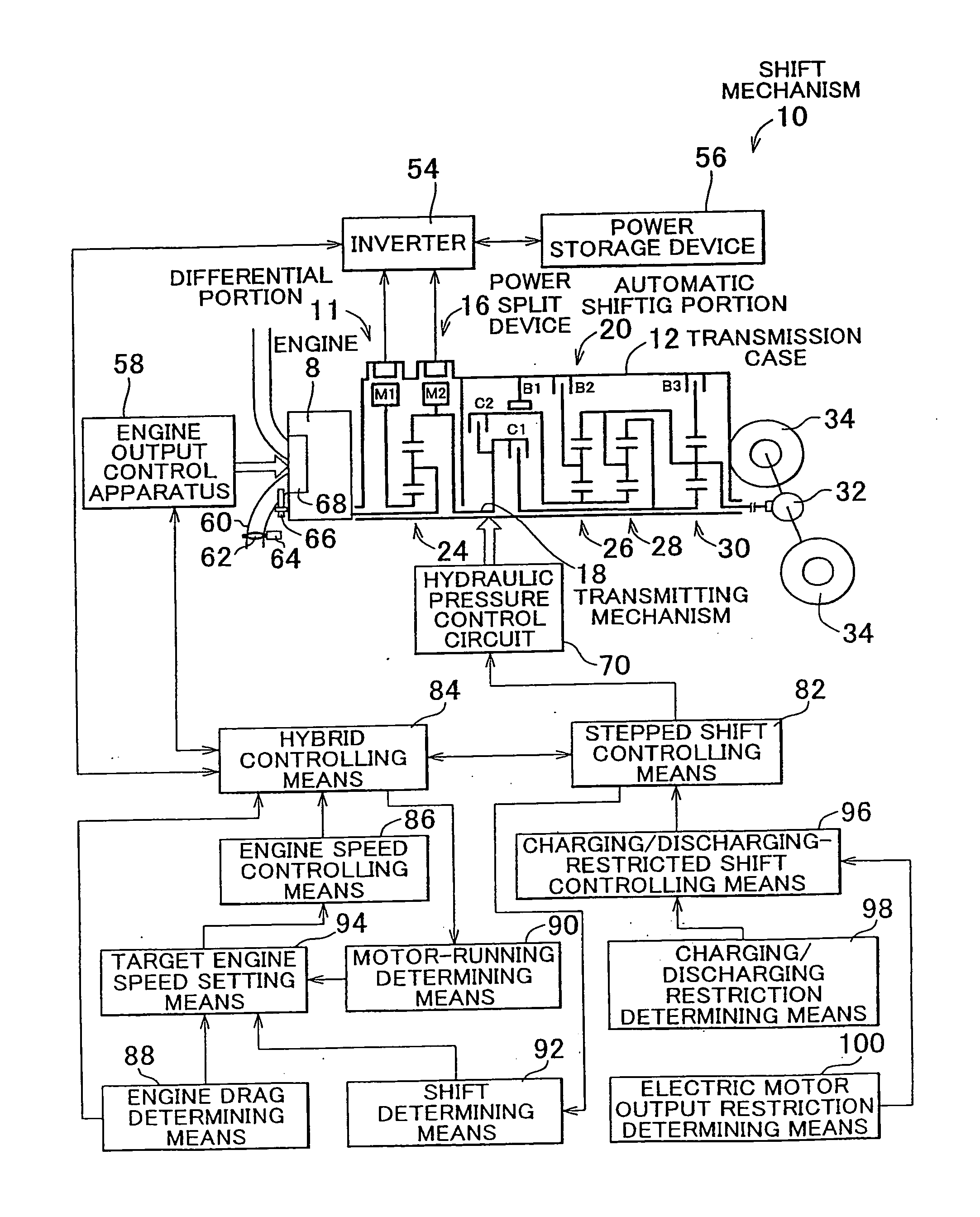
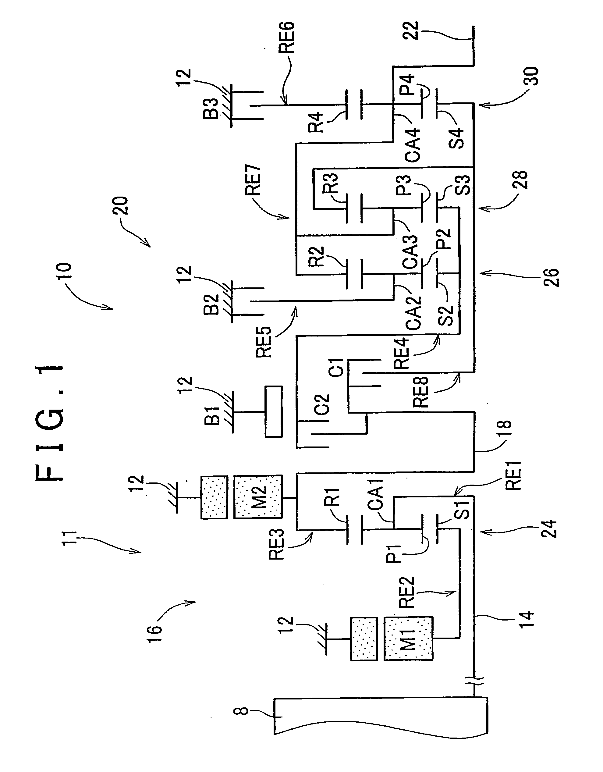
[0054]FIG. 1 is a skeleton view of shift mechanism 10 that constitutes part of a drive system of a hybrid vehicle to which the invention can be applied. In FIG. 1, the shift mechanism 10 includes, in series, an input shaft 14, an electric differential portion (hereinafter simply referred to as “differential portion”) 11, an automatic shifting portion 20, and an output shaft 22. The input shaft 14 is an input rotating member that is arranged inside a transmission case 12, which is a non-rotating member that is attached to the vehicle body (hereinafter this transmission case 12 will simply be referred to as “case 12”), on a common axis. The differential portion 11 is a continuously variable shifting portion that is either directly connected to the input shaft 14 or indirectly connected to the input shaft 14 via a pulsation absorbing d...


PUM


Abstract

In a control apparatus of a vehicular drive system, a charging/discharging-restricted shift control apparatus makes a determination to perform a shift in a shifting portion such that less power is charged to a power storage device or discharged from a power storage device when charging or discharging of the power storage device is restricted than when charging or discharging of the power storage device is not restricted.

Description

INCORPORATION BY REFERENCE[0001]The disclosure of Japanese Patent Application No. 2006-347770 filed on Dec. 25, 2006, including the specification, drawings and abstract is incorporated herein by reference in its entirety.BACKGROUND OF THE INVENTION[0002]1. Field of the Invention[0003]The invention relates to a control apparatus and a control method for a vehicular drive system provided with i) an electric differential portion having a differential mechanism capable of differential operation, and ii) a shifting portion provided in a power transmitting path from the electric differential portion to driving wheels. More particularly, the invention relates to a control apparatus and a control method of a vehicular drive system when charging or discharging of a power storage device is restricted.[0004]2. Description of the Related Art[0005]One well-known control apparatus for a vehicular drive system includes an electric differential portion and a shifting portion. The electric different...

Claims


Application Information

Patent Timeline
IPC IPC(8): B60W10/04B60K1/04B60W10/10F16H37/08F16H48/00H02J7/00G06F19/00B60K6/36B60K6/543B60K6/365B60K6/445B60K6/547B60L50/16B60W10/06B60W10/08B60W10/105B60W10/11B60W10/113B60W10/26B60W20/00F16H61/10F16H61/68F16H61/684F16H61/688F16H63/50
CPCB60K1/02Y10T477/23B60K6/40B60K6/445B60K6/547B60L11/123B60L11/14B60L2220/14B60L2250/30B60L2270/145B60W10/115B60W10/26B60W20/00B60W2520/10F16H3/728F16H61/0213F16H61/686F16H2037/0873F16H2200/0043F16H2200/2012F16H2200/2043Y02T10/6217Y02T10/7077Y02T10/6239F16H2061/0227Y10T477/619Y10T477/606B60K6/365B60L50/61B60L50/16Y02T10/62Y02T10/7072Y02T10/70B60W2510/0676B60W20/13B60W10/08
Inventor SHIBATA, HIROYUKIMATSUBARA, TOORUTABATA, ATSUSHI
Owner TOYOTA JIDOSHA KK
Why Eureka
Try Eureka