
System-in-package having reduced influence between conductor and antenna and method of designing the same

a technology of conductor and antenna, which is applied in the direction of resonant antennas, instruments, solid-state devices, etc., can solve the problems of deterioration of antenna characteristics, increased package size, and inability to simulate and measure which must have excellent radiation characteristics, so as to reduce the influence of the conductor on the characteristics of the antenna. , the effect of minimizing the electromagnetic field

Inactive Publication Date: 2008-06-26
KOREA ADVANCED INST OF SCI & TECH
View PDF6 Cites 53 Cited by
  • Summary
  • Abstract
  • Description
  • Claims
  • Application Information

AI Technical Summary

Benefits of technology

[0017]Accordingly, the present invention has been made keeping in mind the above problems occurring in the prior art, and an object of the present invention is to provide a SiP having reduced influence between a conductor and an antenna, which can minimize an electromagnetic field induced on a planar conductor in a SiP in which the antenna is integrated, thus reducing the influence of the conductor on antenna characteristics.
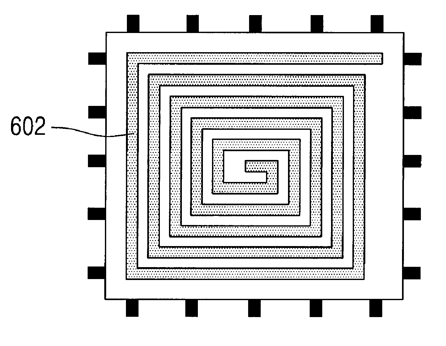
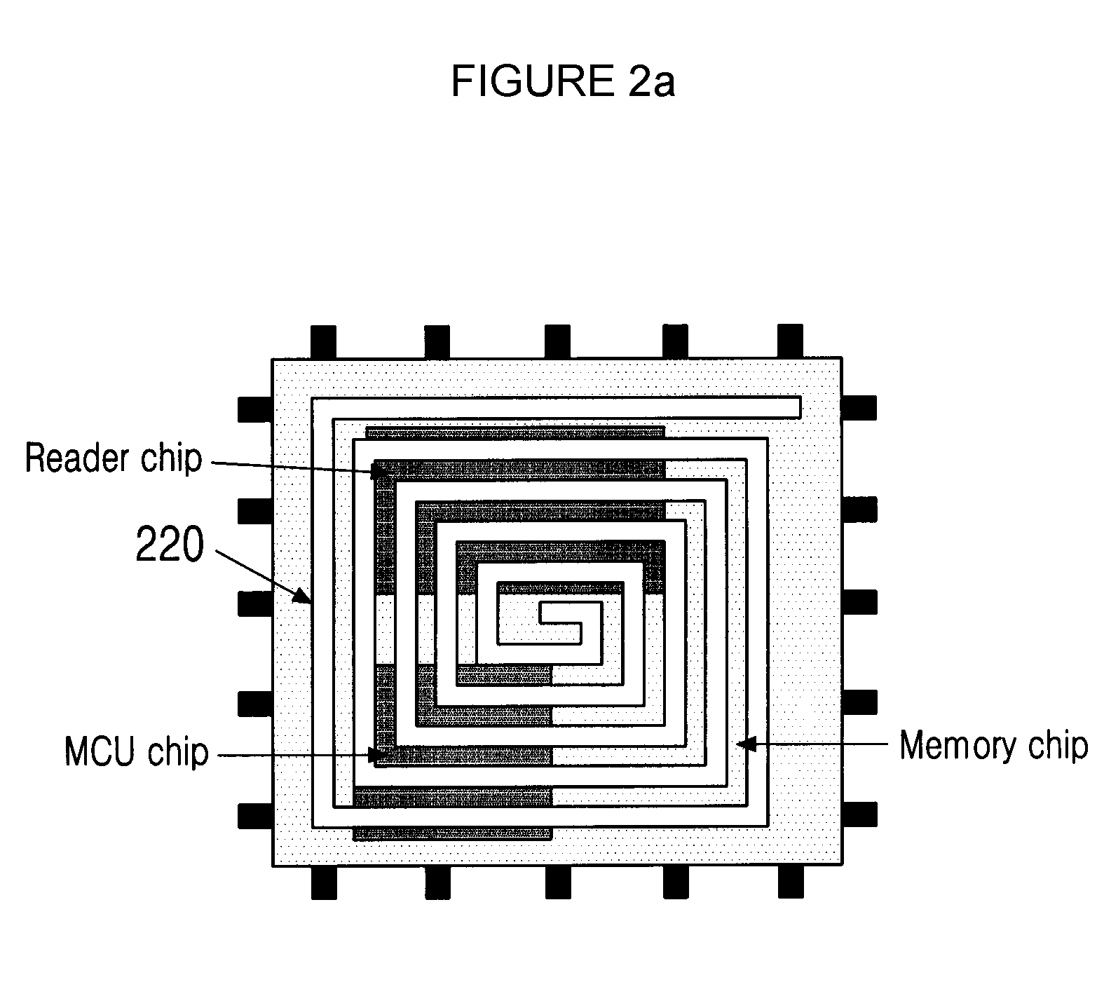
[0020]In accordance with a further aspect of the present invention to accomplish the above object, there is provided a method of designing a System-in-Package (SiP) having a reduced influence between a conductor and an antenna, comprising forming at least one slit in a first planar conductor included in the SiP to reduce current or an electromagnetic field induced on the conductor by current or an electromagnetic field of the antenna integrated in the SiP.
[0023]In accordance with still another aspect of the present invention to accomplish the above object, there is provided a System-in-Package (SiP) having reduced influence between a conductor and an antenna, comprising an antenna configured to function to transmit or receive data and mounted in the SiP to be integrated in the SiP; and a planar conductor having a cutout formed therein at a feeding point of the antenna.

Problems solved by technology

However, a package having such a structure is also problematic in that the operating characteristics desired by the antenna cannot be exhibited in simulation and measurement, and the size of the package is increased.
However, when the metal plane is disposed below the antenna, as shown in FIG. 3B, the antenna on the metal plane is influenced by the metal plane, so that the magnetic flux density is strongly distributed only in the direction in which the metal plane is placed, and thus the characteristics of the antenna, which must have excellent radiation characteristics, are deteriorated.
That is, it can be seen that, when an antenna is integrated in a package, a conductor plane placed below the antenna very negatively influences the operating characteristics of the antenna.

Method used


Image

  • System-in-package having reduced influence between conductor and antenna and method of designing the same
  • System-in-package having reduced influence between conductor and antenna and method of designing the same
  • System-in-package having reduced influence between conductor and antenna and method of designing the same

Examples


Embodiment Construction

[0036]Hereinafter, embodiments of the present invention will be described in detail with reference to the attached drawings. Reference now should be made to the drawings, in which the same reference numerals are used throughout the different drawings to designate the same or similar components. Further, detailed descriptions may be omitted if it is determined that the detailed descriptions of related well-known functions and construction may make the gist of the present invention unclear.

[0037]FIGS. 4A and 4B are views showing a mechanism in which an antenna induces current on a conductor in a conventional SiP.

[0038]FIG. 4A shows the case where an antenna 402 is placed on the top surface of a SiP package, and a planar conductor 404 is placed below the antenna 402 when current Iantenna flows through the antenna 402.

[0039]In this case, a magnetic flux density (H-field) is induced in the direction indicated in the drawing by the current Iantenna flowing through the antenna 402 dependin...


PUM

PropertyMeasurementUnit
Currentaaaaaaaaaa
Electromagnetic fieldaaaaaaaaaa

Abstract

The present invention relates to a SiP having reduced influence between a conductor and an antenna, and a method of designing the SiP. The SiP includes an antenna configured to function to transmit or receive data and mounted in the SiP to be integrated in the SiP, and a first planar conductor having at least one slit formed therein. Therefore, the present invention minimizes the amount of current or electromagnetic field induced on the conductor by the current or electromagnetic field of the antenna, thus reducing the influence of the conductor on the operating characteristics of the antenna.

Description

BACKGROUND OF THE INVENTION[0001]1. Field of the Invention[0002]The present invention relates, in general, to a System-in-Package (SiP) having reduced influence between a conductor and an antenna, and a method of designing the SiP, and, more particularly, to a SiP, which can reduce the influence of a planar conductor on the operating characteristics of an antenna in a SiP in which the antenna is integrated, and a method of designing the SiP.[0003]2. Description of the Related Art[0004]Recently, in mobile devices, such as mobile phones and Personal Digital Assistants (PDAs), technology for System-in-Package (SiP), in which various systems and passive devices are implemented in the form of a single package to realize the small size of the mobile devices, and in which an antenna for data transmission / reception is also integrated in the package, has been variously used.[0005]For example, a Radio-Frequency Identification (RFID) system has been widely used for traffic cards, entrance cont...

Claims


Application Information

Patent Timeline
IPC IPC(8): G06K19/07H01Q17/00
CPCH01Q1/2283Y10T29/49018H01Q9/27H01L2223/6677H01L2224/32225H01L2224/48227H01L2224/48229H01L2224/48237H01L2924/15311H01L2924/19105H01L2924/3025
Inventor KIM, JOUNGHOKIM, GAWONRYU, CHUNG HYUN
Owner KOREA ADVANCED INST OF SCI & TECH
Learn More