
Impedance control for signal interface of a network node

a technology of impedance control and signal interface, which is applied in the field of wired communication systems, can solve the problems of affecting the transmission of signals over the medium, affecting the performance of the network, and taking time to adapt to such changes, so as to minimize or avoid the disruption of signals

Active Publication Date: 2008-06-26
ENTROPIC COMM INC
View PDF11 Cites 12 Cited by
  • Summary
  • Abstract
  • Description
  • Claims
  • Application Information

AI Technical Summary

Problems solved by technology

Mismatches between the impedance of the node and the impedance looking into the network cause reflections.
Such reflections cause a multipath signal environment that impairs passage of the signal over the medium.
Adaptation to such changes takes time to complete.
Sub-optimal compensation of the changed environment can cause degradation in the performance of the network, including a reduction in link margins and an increase in the data error rate.

Method used


Image

  • Impedance control for signal interface of a network node
  • Impedance control for signal interface of a network node
  • Impedance control for signal interface of a network node

Examples


Embodiment Construction

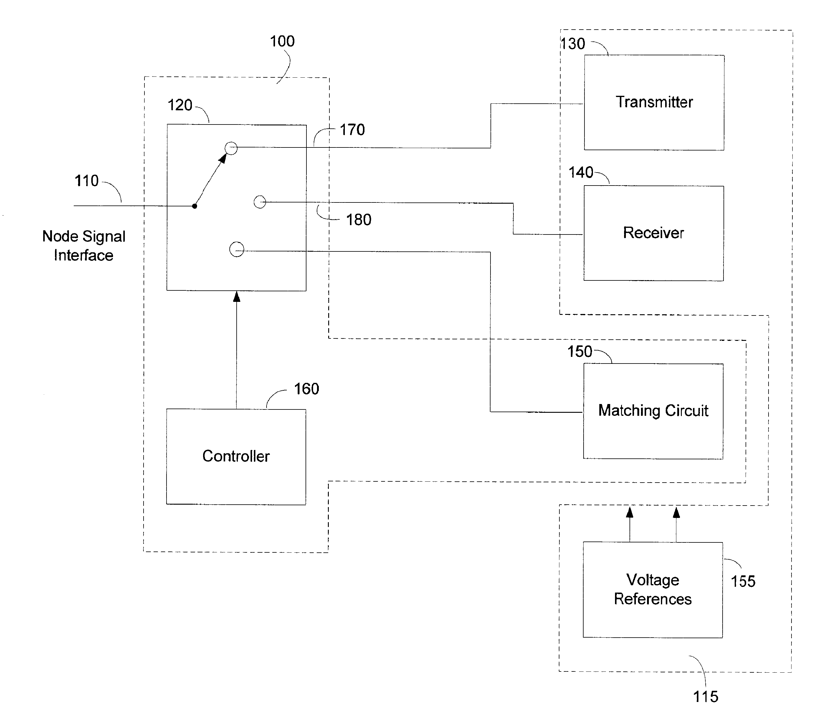
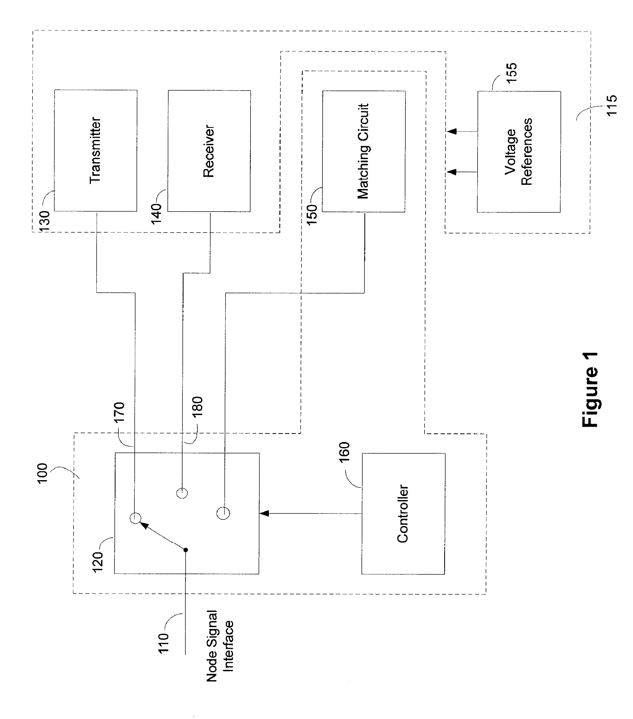
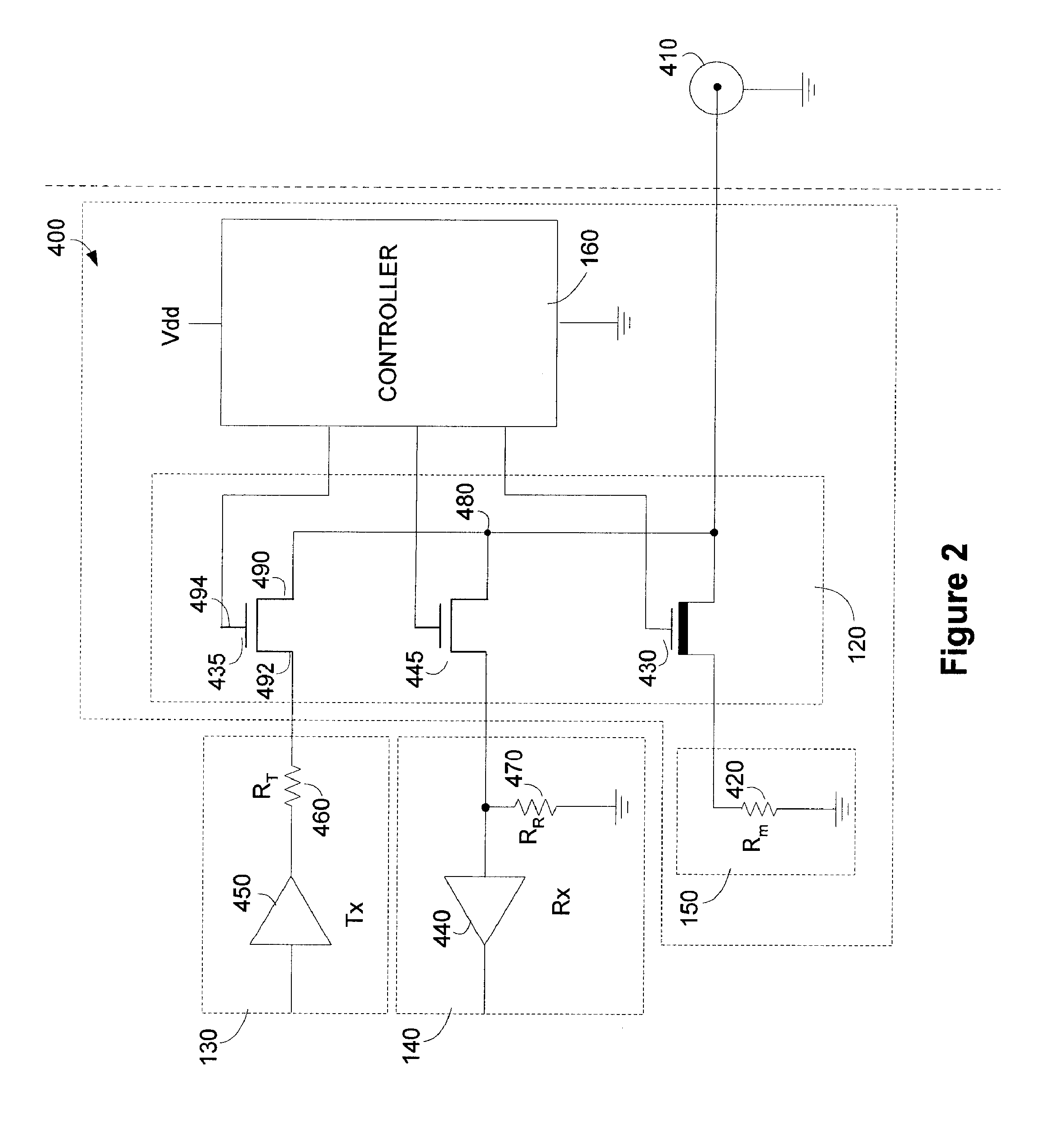
[0018]FIG. 1 shows a block diagram of an Impedance Control Device 100 having a switch 120, a impedance matching circuit 150 and a controller 160. Also shown is a node 115 which includes a transmitter 130, a receiver 140 and a voltage reference 155. A network is connected through a signal interface 110 and the switch 120 to a node 115. With the switch 120 set to connect the transmitter 130 to the signal interface 110 (the switch 120 in the position shown in FIG. 1), the impedance at the signal interface 110 looking back into the switch 120 is preferably matched to the impedance looking in the opposite direction (i.e., away from the switch 120 and into the network). This impedance can be 50 Ohms, 75 Ohms, or any other impedance value, typically depending upon the impedance of the cable or wire connected to the network. The position of the switch 120 is selected by a controller 160. The controller 160 determines whether the node 115 is in transmit and receive mode and selects the posit...


PUM


Abstract

The terminating impedance of a networked device in a wired communication channel is controlled to avoid an impedance discontinuity when power is applied and removed from the node or other event occurs that would change the impedance of the signal interface. When the node transmits or receives signals using the communication channel, the transmit or receive device presents a matched termination to the channel. When power is removed or the device is reset, the transmit and receive circuitry is not operational and the matched impedance is therefore maintained by a separate device. The impedance may be varied slowly from a match to a high impedance to allow other devices in the network to adapt to the change in multipath environment that results from the impedance change. Alternatively, the signal interface can be switched to a passive static impedance that is maintained while power is off or the disrupting event occurs.

Description

CROSS REFERENCES TO RELATED APPLICATIONS[0001]This application claims the benefit of U.S. Provisional Application No. 60 / 870,847 filed Dec. 20, 2006, hereby incorporated by reference herein in its entirety.BACKGROUND[0002]1. Field[0003]The invention relates to wired communication systems and specifically to controlling the impedance of an electrical signal interface of a network.[0004]2. Background[0005]Consider several communication nodes that are part of the same coaxial cable network or other wired network. Each node connecting to the network presents an impedance at the point of connection. Mismatches between the impedance of the node and the impedance looking into the network cause reflections. Such reflections cause a multipath signal environment that impairs passage of the signal over the medium. The input and output of the nodes include active circuitry that changes its impedance when power is applied and removed. The impedance can also change when other events occur. For ex...

Claims


Application Information

Patent Timeline
Patent Type & Authority Applications(United States)
IPC IPC(8): H03K19/08H04L12/50
CPCH04B1/44G06F13/4086
Inventor WARNER, EDWARD J.MOUGHABGHAB, RAED V.LANDRY, MICHAEL W.
Owner ENTROPIC COMM INC
Learn More