

Display device
a display device and display technology, applied in the field of display devices, can solve the problems of inability to cope with a variation in each display element, and achieve the effects of reducing the detection time, and reducing the number of display elements
- Summary
- Abstract
- Description
- Claims
- Application Information
AI Technical Summary
Benefits of technology
Problems solved by technology
Method used
Image

Examples
embodiment 1
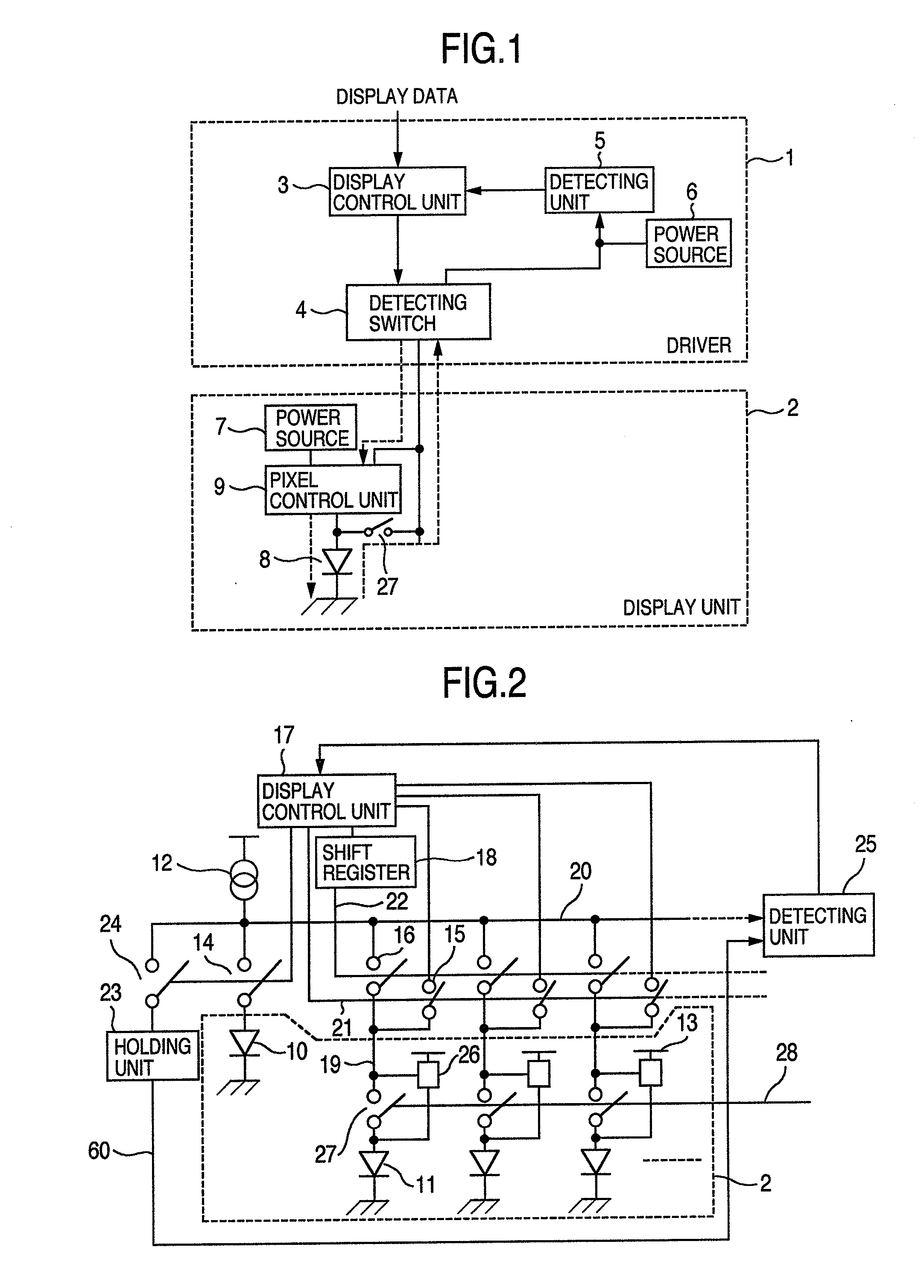
[0027]FIG. 1 is a whole constructional diagram in a display panel unit. The display panel unit is constructed by a driver 1 and a display unit 2. The driver 1 includes a display control unit 3, a detecting switch 4, a detecting unit 5, and a power source 6 for detection. The display unit 2 includes a power source 7 for display, a display element 8, and a pixel control unit 9.
[0028]In FIG. 1, display data from an outside is inputted to the display control unit 3 of the driver 1. The display control unit 3 makes timing control and signal control of the input display data. A signal flow in the driver 1 is mainly classified into the following three kinds of flow: a display path; a detection path; and a correction path.
[0029]The display path is a flow in which the input display data passes through the display control unit 3 and the detecting switch 4 in the driver 1 and enters the display unit 2 and the display element 8 is driven by the displaying power source 7 through the pixel contro...
embodiment 2
[0056]FIG. 9 shows an embodiment having another construction regarding FIG. 5 in the embodiment 1. According to this construction, a plurality of reference elements are detected in a lump. Assuming that n reference elements are provided, the number of display elements to be detected is equal to n. By increasing a current supply amount of the current source to n times, the detecting precision is increased to n times as compared with the case of detecting one reference element.
[0057]In FIG. 9, the reference line 60 is connected to the holding unit 23 for holding the reference voltage. The common current source 62 is connected to the detection line 61. The display elements (A 50, B 51, C 52), a display element D 53, and all of other pixels are connected by the switches 63. A reference element A 56 and a reference element B 57 are connected by the switch 64. The holding unit 23 is connected by the switch 65. The switches 63, 64, and 65 are controlled by the display control unit 17.
[0058...
embodiment 3
[0060]FIG. 10 shows an embodiment having another construction regarding FIG. 5 in the embodiment 1. According to this construction, no reference elements are provided besides the display elements, two current sources are provided, the adjacent display elements are compared, and a balance between the display elements is held. All of the display elements can be connected to a reference line 40 and a detection line 41 by a switch 42 and switches 43, respectively. As current sources, current sources 44 and 45 are independently provided for the reference line 40 and the detection line 41. The switches 42 and 43 are controlled by the display control unit 17.
[0061]Subsequently, the operation of FIG. 10 will be described. In the case of detecting the states of the display elements, the display elements A 50 and B 51 are compared and, subsequently, the display elements B 51 and C 52 are compared in this order. The display element A 50 is connected to the reference line 40 by the switch 42. T...
PUM
 Abstract
Description
Claims
Application Information