
Method and apparatus for driving plasma display panel

a technology of plasma display panel and plasma display, which is applied in the direction of instruments, television systems, static indicating devices, etc., can solve the problems of increasing the ramp voltage of the reset period, the driving time of the pdp becomes longer, and the ramp voltage becomes insufficient, so as to reduce the discharge delay, reduce the driving margin, and ensure the effect of discharge stability

Inactive Publication Date: 2008-06-26
LG ELECTRONICS INC
View PDF4 Cites 1 Cited by
  • Summary
  • Abstract
  • Description
  • Claims
  • Application Information

AI Technical Summary

Benefits of technology

This approach reduces discharge delay, enhances the driving margin, and stabilizes sustain discharge, enabling single scan operation and improved picture quality by effectively managing wall charges.

Problems solved by technology

However, as the subfield is added for rising the pixel or improving the picture quality, the address driving time becomes longer and the driving time for the PDP becomes insufficient.
However, if the content of Xe is increased like this, the ramp voltage of the reset period increases and the discharge is delayed.
Specially, as the value of the address jitter is increased, the scan period and the address period is increased, PDP can not be drived by single scan, the driving margin becomes smaller, and the sustain work becomes unstable.

Method used


Image

  • Method and apparatus for driving plasma display panel
  • Method and apparatus for driving plasma display panel
  • Method and apparatus for driving plasma display panel

Examples


Embodiment Construction

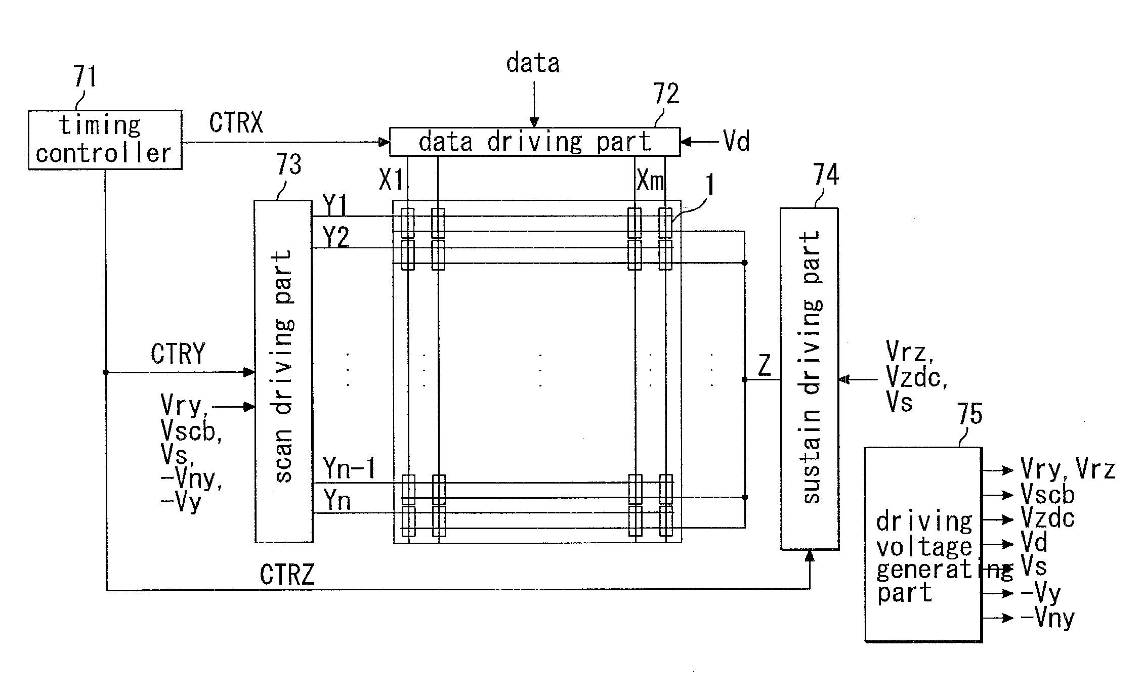
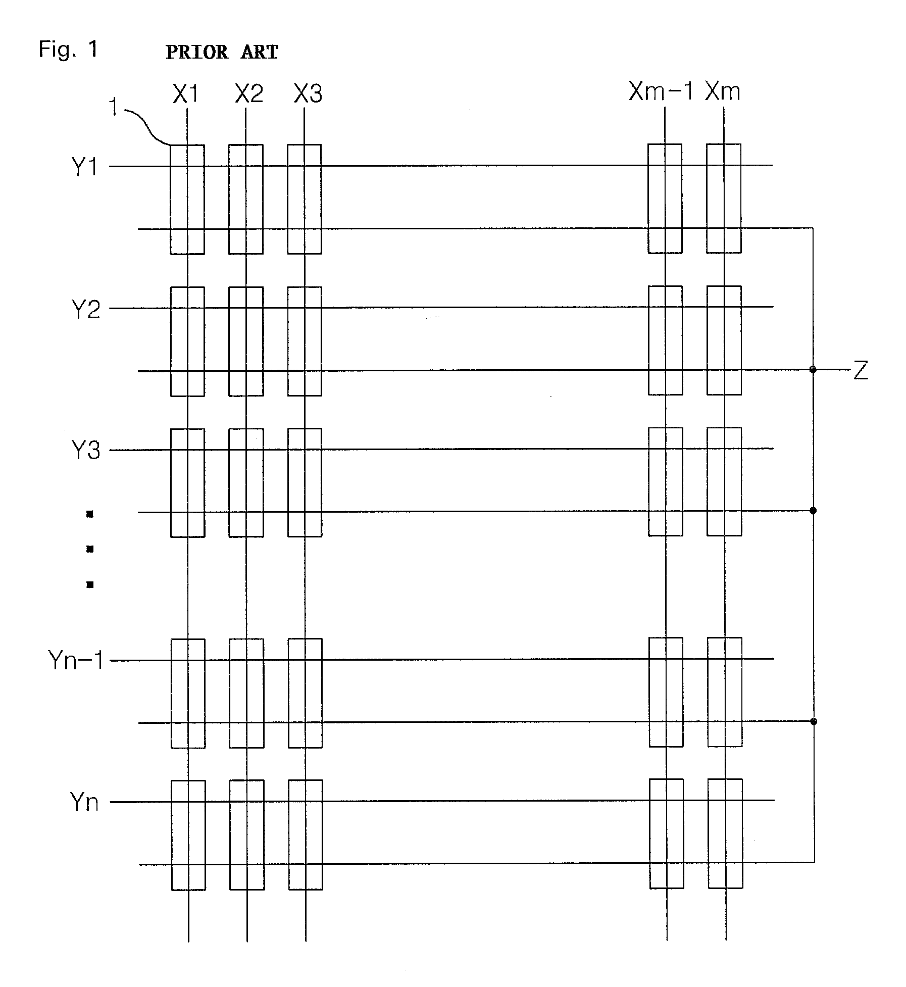
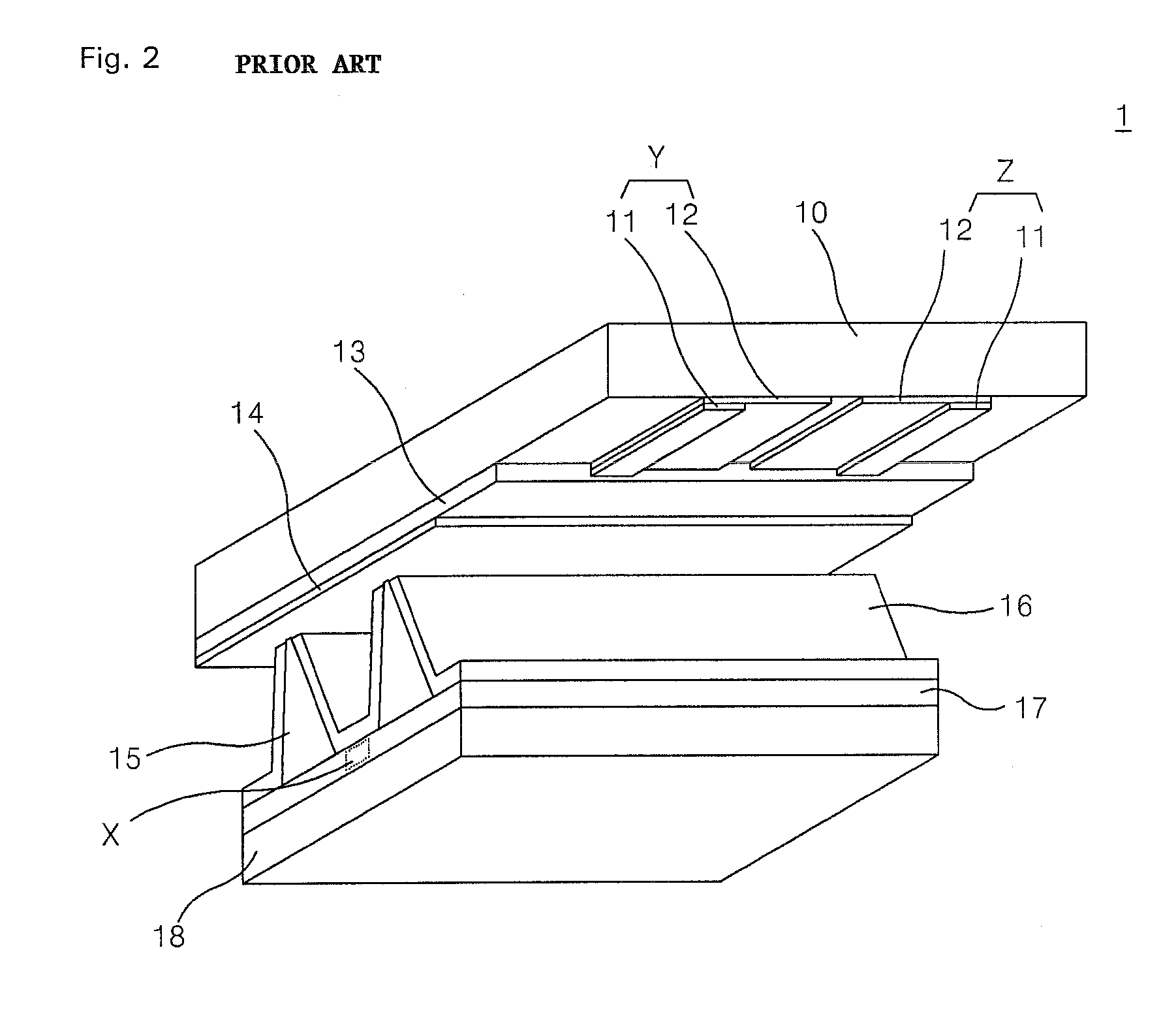
[0045]According to an aspect of the present invention, a method for driving a plasma display panel in which pluralities of first electrodes and second electrodes are arranged parallel and to each other adjacently on an upper substrate, a plurality of third electrodes is arranged to cross the pairs of first and second electrodes at electrode crossing areas and define corresponding discharge cells at the electrode crossing areas on an lower substrate, wherein said method for driving a plasma display panel comprises steps of: forming wall charges on the upper and lower substrate by applying first rising ramp waveform to said first electrodes during a first period of a reset period; erasing partly the wall charges which are formed on the upper substrate by applying second rising ramp waveform to said second electrodes during a second period of a reset period; erasing partly the wall charges which are formed on the upper and lower substrates by applying falling ramp waveform to said firs...


PUM


Abstract

The present invention relates to a plasma display panel, and more specifically, a method and an apparatus for driving a plasma display panel. According to the present invention, a method for driving a plasma display panel in which pluralities of first electrodes and second electrodes are arranged parallel and to each other adjacently on an upper substrate, a plurality of third electrodes is arranged to cross the pairs of first and second electrodes at electrode crossing areas and define corresponding discharge cells at the electrode crossing areas on an lower substrate, wherein said method for driving a plasma display panel comprises steps of: forming wall charges on the upper and lower substrate by applying first rising ramp waveform to said first electrodes during a first period of a reset period; erasing partly the wall charges which are formed on the upper substrate by applying second rising ramp waveform to said second electrodes during a second period of a reset period; erasing partly the wall charges which are formed on the upper and lower substrates by applying falling ramp waveform to said first and second electrodes during a third period of a reset period; selecting the discharge cells by applying data voltage to said third electrodes and applying scan voltage to said first electrodes during a address period; and displaying an image on screen by applying sustain voltage to said first and second electrodes alternatively during a sustain period.

Description

[0001]This application is a Continuation Application of a Nonprovisional application Ser. No. 10 / 850,437, filed on May 21, 2004, which claims priority under 35 U.S.C. § 119(a) on Patent Application No. 10-2003-033106 filed in Korea on May 23, 2003, the entire contents of which are hereby incorporated by reference.BACKGROUND OF THE INVENTION[0002]1. Field of the Invention[0003]The present invention relates to a plasma display panel, and more specifically, a method and an apparatus for driving a plasma display panel.[0004]2. Description of the Background Art[0005]A plasma display panel (hereinafter, referred to as “PDP”) displays images including characters or graphics since fluorescent material is emitted by ultraviolet rays of 147 nm occurring when inert mixed gases of He+Xe, Ne+Xe, He+Ne+Xe, etc. are discharged. It is easy for this PDP to be made thin and large. The PDP also provides an improved picture quality due to recent advanced technology. In particular, in a 3-electrode AC s...

Claims


Application Information

Patent Timeline
Patent Type & Authority Applications(United States)
IPC IPC(8): G09G3/28H04N5/66G09G3/20G09G3/288G09G3/291G09G3/292G09G3/293G09G3/294G09G3/298
CPCG09G3/2927G09G2310/066G09G3/296G09G3/293
Inventor KIM, OE DONGKIM, JUNG HUN
Owner LG ELECTRONICS INC
Features
  • Generate Ideas
  • Intellectual Property
  • Life Sciences
  • Materials
  • Tech Scout
  • Unparalleled Data Quality
  • Higher Quality Content
  • 60% Fewer Hallucinations
Learn More