Image monitoring system for preventing confidential information outflow, image monitoring method, and computer image monitoring program stored on a computer readable medium

Active Publication Date: 2008-06-26
KONICA MINOLTA BUSINESS TECH INC
View PDF5 Cites 18 Cited by
  • Summary
  • Abstract
  • Description
  • Claims
  • Application Information

AI Technical Summary

Benefits of technology

[0008]The present invention is made to solve the aforementioned problem. An object of the present invention is to provide an image m

Problems solved by technology

In addition, the detection of unauthorized car use is disabled when the car passe

Method used


Image

  • Image monitoring system for preventing confidential information outflow, image monitoring method, and computer image monitoring program stored on a computer readable medium
  • Image monitoring system for preventing confidential information outflow, image monitoring method, and computer image monitoring program stored on a computer readable medium
  • Image monitoring system for preventing confidential information outflow, image monitoring method, and computer image monitoring program stored on a computer readable medium

Examples


Embodiment Construction

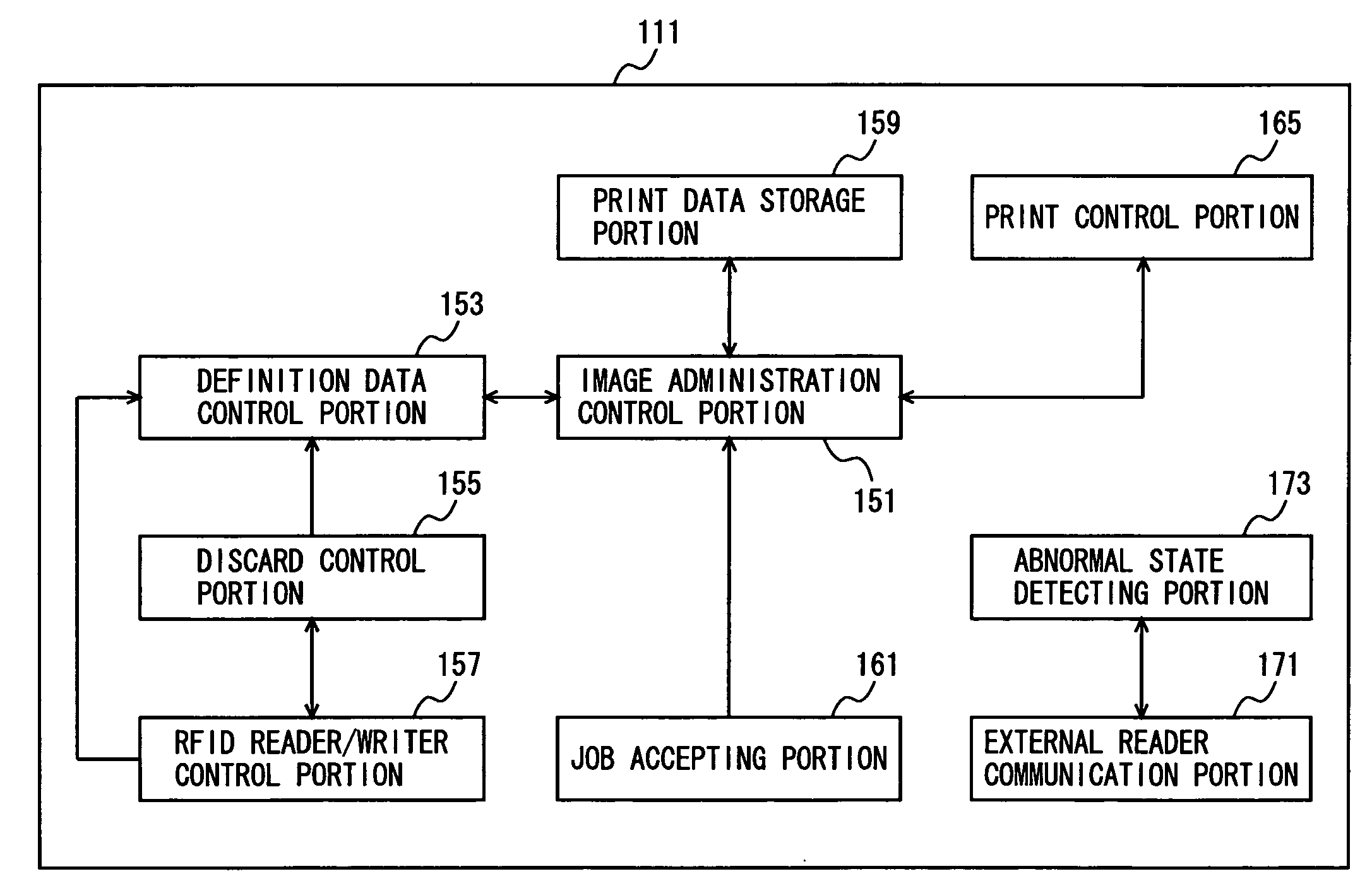
[0036]An embodiment of the present invention will be described below with reference to the drawings. In the following description, the same or corresponding parts are denoted by the same reference characters. Their names and functions are also the same. Thus, a detailed description thereof will not be repeated.

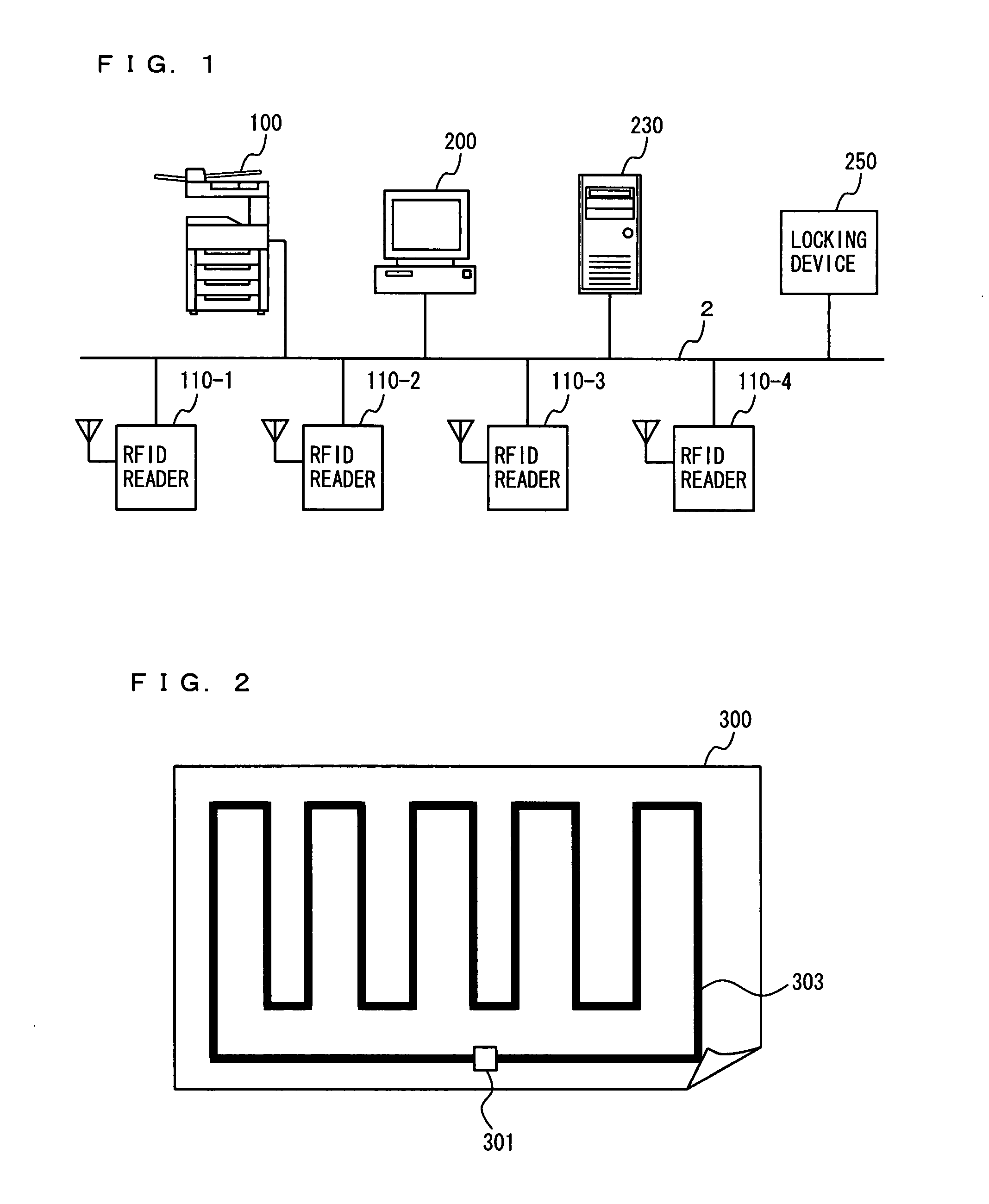
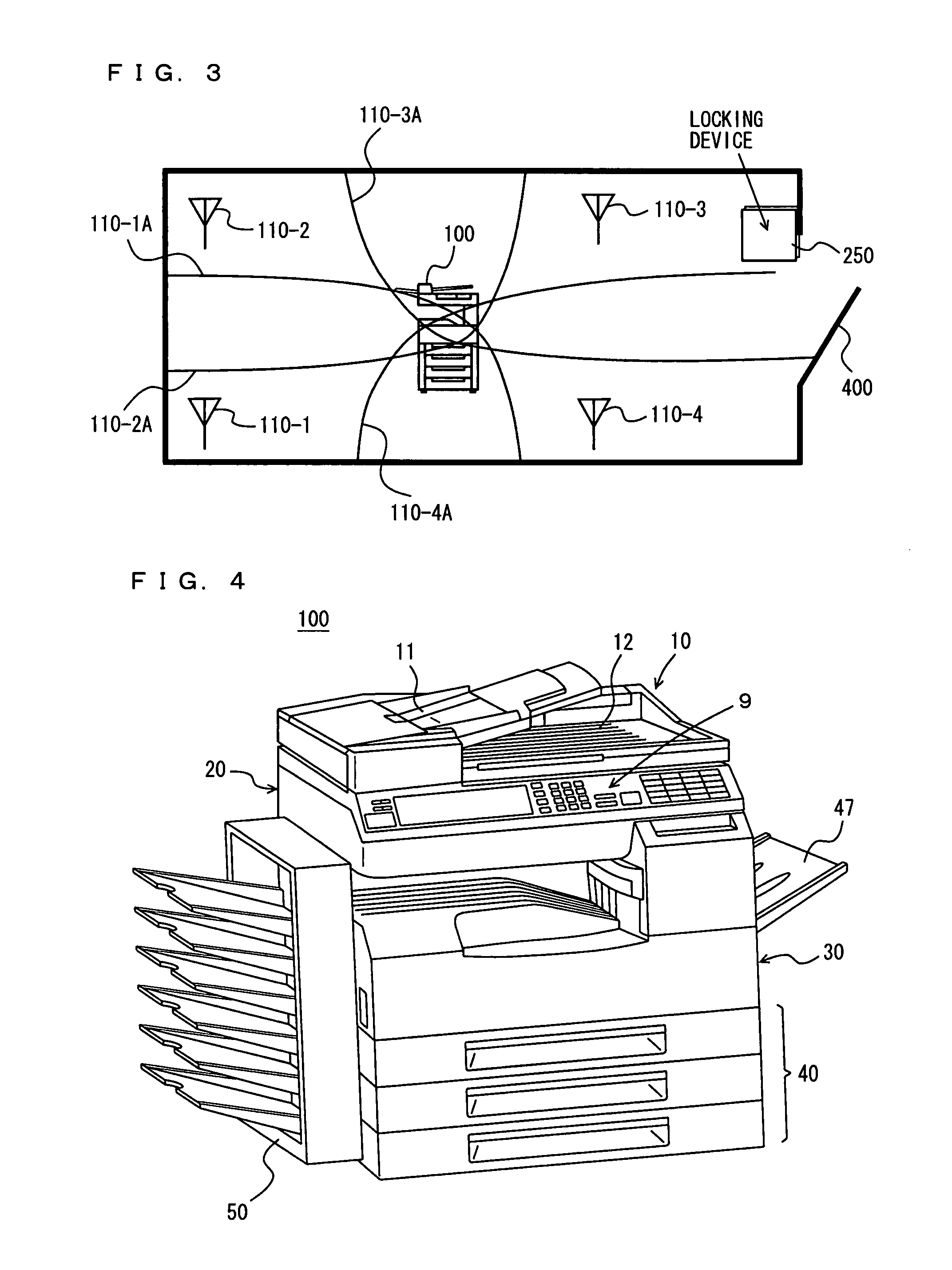
[0037]FIG. 1 is a schematic diagram of an image monitoring system according to an embodiment of the present invention. Referring to FIG. 1, an image monitoring system 1 includes a multi-function peripheral (herein referred to as “MFP”) 100 as an image-forming apparatus, four RFID readers 110-1 to 110-4 as monitoring means, a personal computer (hereinafter referred to as “PC”) 200, a server 230, and a locking device 250, all of which are connected to a network 2.

[0038]PC 200 and server 230 are usual computers. The hardware structure and function of the computers are well known and therefore will not be repeated here. Locking device 250 has the function of locking the doors of t...


PUM


Abstract

In order to prevent a sheet of paper on which confidential information is formed as an image from being taken out, an MFP has a print data accepting portion to accept print data, an image-forming portion to form an image based on the print data onto a sheet of paper having an RFID tag provided with a memory and a data communication portion, an RFID reader/writer control portion to acquire tag identification information for identifying the RFID tag provided by the sheet of paper on which the image is formed based on the print data, a definition data control portion to store definition data including the acquired tag identification information, an external reader communication portion to communicate with a communicable RFID reader, and an abnormal state detecting portion to judge as an abnormal state the case where the external reader communication portion communicating with a communicable RFID reader is detected to be non-communicable with the RFID tag specified by the tag identification information included in the definition data.

Description

[0001]This application is based on Japanese Patent Application No. 2006-344811 filed with Japan Patent Office on Dec. 21, 2006, the entire content of which is hereby incorporated by reference.BACKGROUND OF THE INVENTION[0002]1. Field of the Invention[0003]The present invention relates to an image monitoring system, an image monitoring method, and an image monitoring program stored on a computer readable medium, and more particularly, to an image monitoring system for preventing confidential information outflow, an image monitoring method for preventing confidential information outflow, and an image monitoring program stored on a computer readable medium.[0004]2. Description of the Related Art[0005]In recent years, there is a need for prevention of leakage of confidential information. This is not limited to confidential information recorded in computers as electronic information; when confidential information is formed as images onto sheets of paper, these sheets of paper are need to...

Claims


Application Information

Patent Timeline
IPC IPC(8): H04N1/00
CPCH04N1/00342H04N1/00859H04N1/00872H04N1/446H04N1/4413H04N1/444H04N1/32138
Inventor ISHIMARU, KOHJI
Owner KONICA MINOLTA BUSINESS TECH INC
Why Eureka
Try Eureka