Turning tool, and a basic body and a shim plate for a turning tool

a technology of turning tool and shim plate, which is applied in the field of turning tools, can solve the problems of unstable fixing of turning inserts, unreliability, and lack of locking capability of turning inserts, and achieve the effect of improving stability, continuing simple and cost-effective manufactur

Active Publication Date: 2008-06-26
SANDVIK INTELLECTUAL PROPERTY AB
View PDF11 Cites 29 Cited by
  • Summary
  • Abstract
  • Description
  • Claims
  • Application Information

AI Technical Summary

Benefits of technology

[0017]The present invention aims at obviating the above-mentioned shortcomings of previously known turning tools and at providing an improved turning tool of the type that makes use of shim plates to determine the tilt angle of the cutting tooth. Therefore, an object of the invention to provide a tool, the turning insert of which is kept stably fixed in the desired, predetermined position thereof also under varying stresses on the insert.

Problems solved by technology

A disadvantage of the known tool construction is that the fixation of the turning insert may become unstable and unreliable, among other things as a consequence of the fact that the only active structure that, besides the tightening screw, counteracts turning of the turning insert is the two upper, converging side support surfaces in the pocket.
Thus, the underside of the turning insert and the upperside of the shim plate are plane and smooth, and therefore they lack the capability of locking the turning insert.
Even if the stability problems are moderate at the entering of the turning insert into the workpiece, as the cutting forces aim to turn the turning insert in such a way that the forces essentially are carried by the primary, long side support surface, the problems become marked when the turning insert leaves the workpiece and is subjected to forces that primarily are to be carried by the short, secondary side support surface.
In the latter case, the risk is large that the short contact surface of the turning insert slides along the co-operating, secondary side support surface during tensioning of the tightening screw and dislodging of the turning insert.
If the turning insert on and off is dislodged from the desired, predetermined position thereof, the result becomes an impaired dimensional accuracy of the thread turned.
Moreover, in polar cases, breakdowns may occur.
However, in these cases, the tools lack shim plates.
However, in this case, the shim plate is locked in relation to the basic body as well as the turning insert via serration surfaces, which individually include a plurality of ridges and grooves, and furthermore, support for the side surfaces of the turning insert are lacking.
For these reasons, the manufacture of the tool is complicated at the same time as the risk of form defects in the turning insert as well as the shim plate may give rise to poor machining precision of the tool.

Method used


Image

  • Turning tool, and a basic body and a shim plate for a turning tool
  • Turning tool, and a basic body and a shim plate for a turning tool
  • Turning tool, and a basic body and a shim plate for a turning tool

Examples


Embodiment Construction

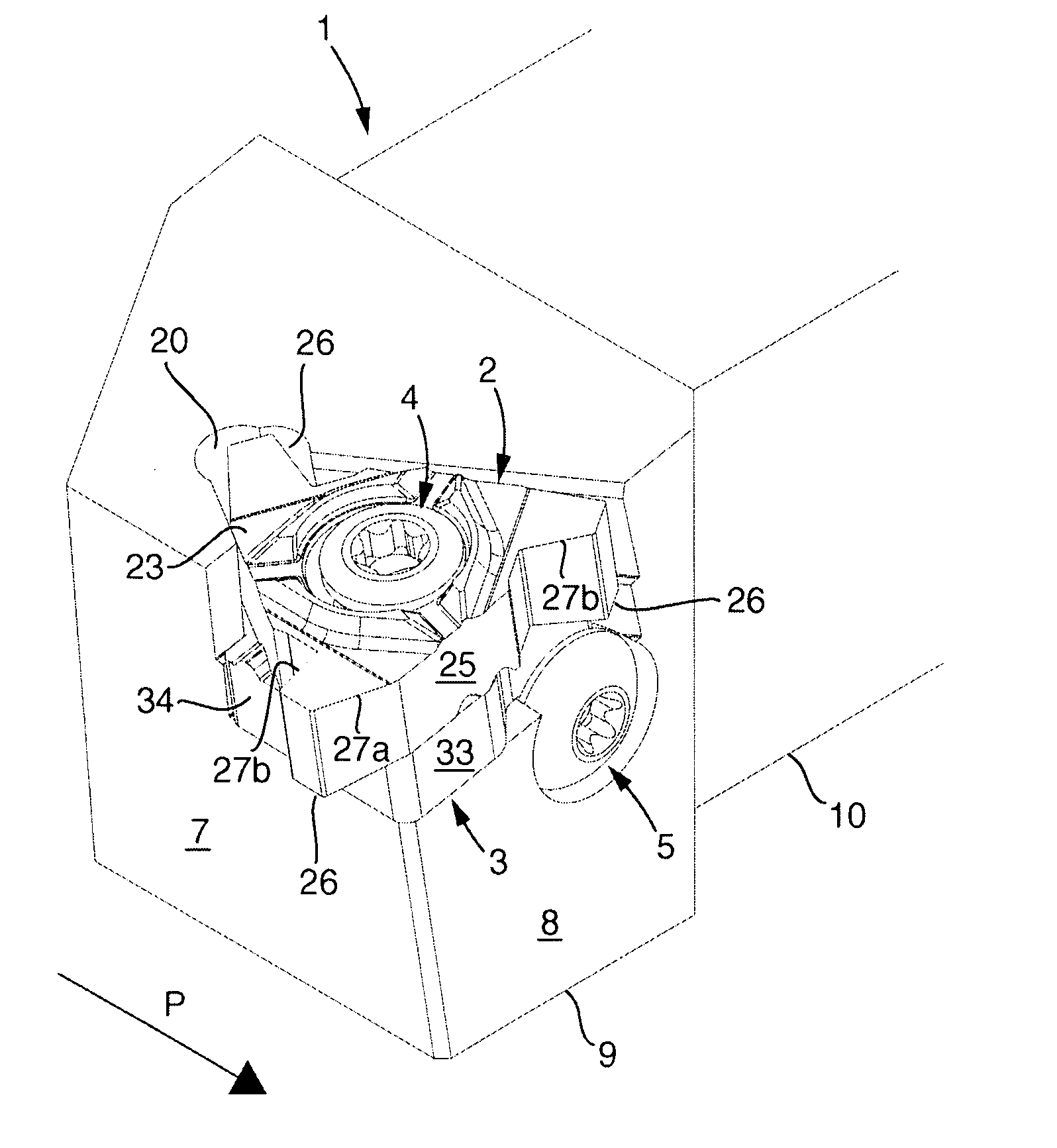
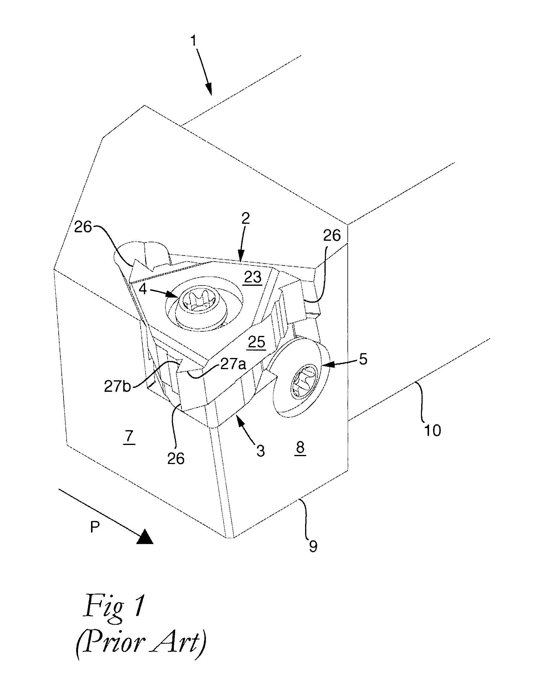
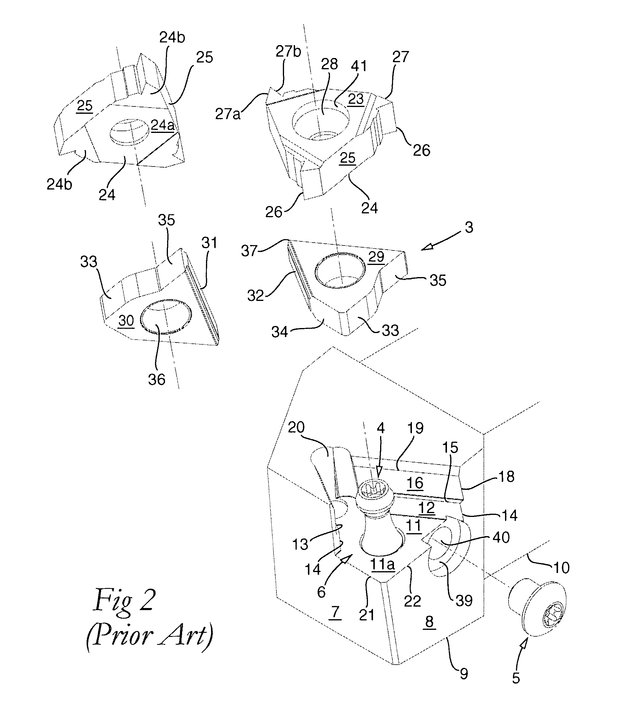
[0037]The parts of the new tool according to FIGS. 6-14 having the counterpart thereof in the related art tool according to FIGS. 1-5 have been given the same reference designations as in FIGS. 1-5, and are not described in more detail below.

[0038]Generally, the turning inserts of the tool are manufactured from cemented carbide or another hard and wear-resistant material, while the basic body is manufactured from steel or the like. The shim plate may also advantageously be manufactured from cemented carbide, although steel is also possible as a material. When the turning insert and the shim plate are manufactured from cemented carbide, the same may be ground as well as directly pressed, i.e., unground. It is also possible to grind the turning insert and leave the shim plate unground, or vice versa.

[0039]The invention is based on a combination of two principal measures, one of which includes connecting the turning insert with the shim plate via an interface that includes female-like ...


PUM

PropertyMeasurementUnit
angleaaaaaaaaaa
anglesaaaaaaaaaa
acute anglesaaaaaaaaaa

Abstract

A turning tool including a basic body having a pocket, a shim plate mounted in the pocket, and an indexable turning insert mounted in the pocket. The pocket opens in a front surface and in a side surface of the basic body, and accommodates two spaces spaced-apart level-wise, a lower space housing the shim plate and delimited by a bottom surface and two side support surfaces, which form an acute angle with each other, one of which is a primary side support surface and the other one a secondary side support surface, and an upper space housing the turning insert. The shim plate includes an upperside and an underside between which a pair of primary and secondary contact surfaces extend, which form an acute angle with each other and are urged against the primary and secondary side support surfaces in the pocket, as well as a pair of inactive surfaces extend in the form of an outer end surface and an outer side limiting surface, which together delimit a supporting corner section of the shim plate. The turning insert has a triangular basic shape and includes an upperside, an underside resting against the upperside of the shim plate, and three side surfaces that are situated in a first imaginary, equilateral triangle and therefore converge in pairs at an angle of 60° toward corners in which cutting edges are included. First and second tightening elements are arranged to detachably fix the shim plate and the turning insert individually. The secondary side support surface of the pocket is formed on a lug having a top surface situated under the turning insert. Respective acute angles (ε, γ) between the primary and secondary side support surfaces of the pocket, and the primary and secondary contact surfaces of the shim plate, are smaller than 60°. The underside of the turning insert and the upperside of the shim plate are engaged with each other via an interface that includes female-like and male-like engagement members, which are in engagement with each other to prevent turning of the turning insert.

Description

[0001]This application claims priority under 35 U.S.C. §119 to Swedish Patent Application No. 0602808-8, filed on Dec. 21, 2006, the disclosure of which is incorporated by reference herein in its entirety.FIELD OF THE INVENTION[0002]The present invention relates generally to a turning tool for chip removing machining of the type that includes a basic body having a pocket in which a shim plate and an indexable turning insert are mounted. The pocket opens in a front surface and a side surface of the basic body, and accommodates two spaces spaced-apart level-wise, a lower one of which houses the shim plate and is delimited by a bottom surface and two side support surfaces, which form an acute angle with each other, and one of which is a primary side support surface and the other one a secondary side support surface, while an upper space houses the turning insert. The shim plate includes an upperside and an underside between which a number of side surfaces extend, viz. a pair of primary...

Claims


Application Information

Patent Timeline
Patent Type & Authority Applications(United States)
IPC IPC(8): B23B27/00B23P15/28B23B27/16B26D1/00
CPCB23B27/065B23B27/1622B23B2200/049B23B2200/165Y10T407/1932B23B2205/16Y10T407/23Y10T407/22Y10T407/2274B23B2205/12B23B27/02B23B27/04B23B27/16B23B27/1614B23B29/16B23G5/00
Inventor ANDERSSON, CLAESJANSSON, GUNNAR
Owner SANDVIK INTELLECTUAL PROPERTY AB
Why Eureka
Try Eureka