

Electrical terminal
- Summary
- Abstract
- Description
- Claims
- Application Information
AI Technical Summary
Benefits of technology
Problems solved by technology
Method used
Image

Examples
Embodiment Construction
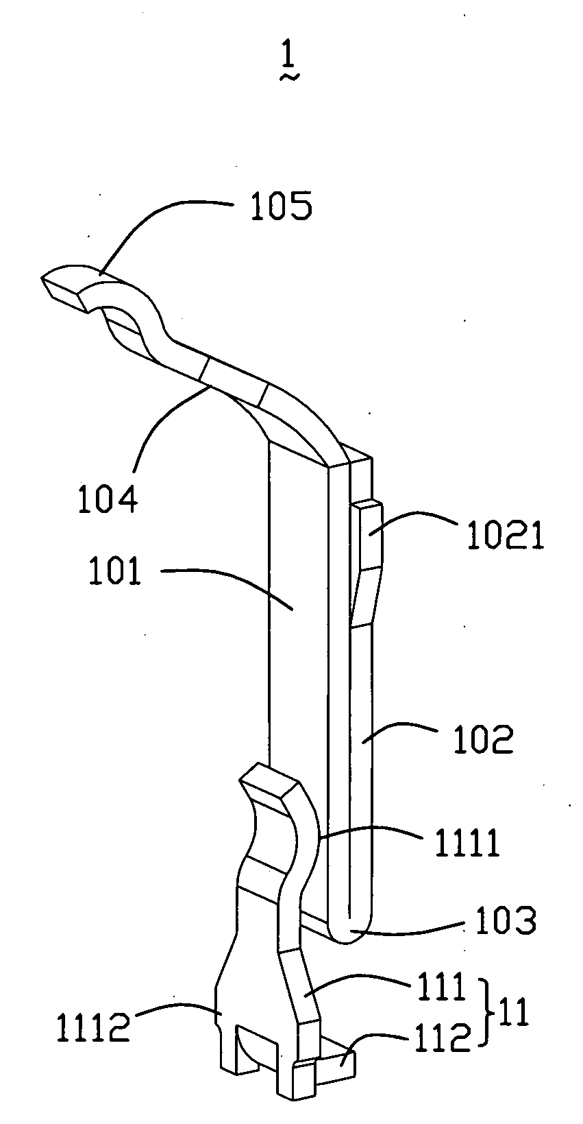
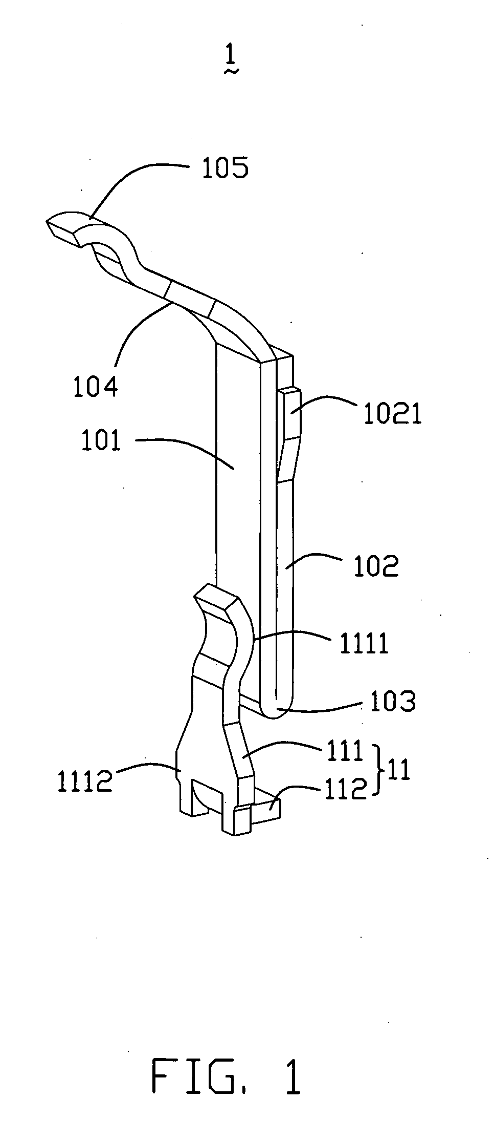
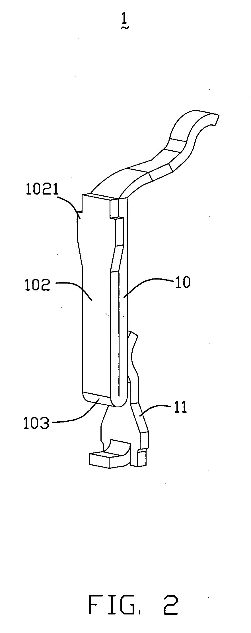
[0013]Reference will now be made to the drawing figures to describe the present invention in detail. FIGS. 1-2 show an electrical terminal 1 used in an electrical connector (not shown) for electrical connecting an electronic package such as IC package (not shown) with a circuit substrate such as a printed circuit board (not shown). The electrical terminal 1 is formed by stamping and forming a metal plate, and has a resilient arm 10, and a separate solder member 11 resiliently contacting with the resilient arm 10.
[0014]The resilient arm 10 has a base portion (not labeled) including a middle portion 101, an inserting portion 102 adjacent to the middle portion 101, and a curved section 103 interconnected a lower end of the middle portion 101 and the inserting portion 102. The middle portion 101 is a substantially rectangular plate extending in a direction perpendicular to the printed circuit board, and has an upper and a lower end (not labeled) formed thereon. The inserting portion 102...
PUM
 Abstract
Description
Claims
Application Information