Techniques for interconnecting electronic cabinet frames

a technology of electronic cabinet and frame, which is applied in the direction of electrical apparatus casing/cabinet/drawer, sectional furniture, support structure mounting, etc., can solve the problems of not being able to fit through a doorway or around a corner of a hallway, the manufacturer no longer has the option of subsequently separating the frame, and the equipment may exceed the internal volume provided. , to achieve the effect of preventing the frame from splaying, reducing the demand for larg

Active Publication Date: 2005-10-18
EMC IP HLDG CO LLC
View PDF8 Cites 25 Cited by
  • Summary
  • Abstract
  • Description
  • Claims
  • Application Information

AI Technical Summary

Benefits of technology

[0008]The invention is directed to techniques for interconnecting electronic cabinet frames using a set of latch subassemblies. Such subassemblies provide a manufacturer with flexibility to selectively interconnect and disconnect electronic cabinet frames without handling any nuts or bolts. Accordingly, the manufacturer is capable of subsequently separating electronic cabinet frames to accommodate particular situations (e.g., narrow facilities at a customer location, a reduced demand for large-scale equipment configurations, etc.) as well as avoid the risks associated with handling loose hardware (e.g., avoid loosing nuts and bolts during shipping, dropping a nut or a bolt into electronic circuitry, etc.).
[0009]One embodiment of the invention is directed to an electronic system having electronic equipment (e.g., data storage equipment), and an electronic cabinet assembly which is configured to support the electronic equipment. The electronic cabinet assembly includes a first electronic cabinet frame defining a first set of electronic equipment bays to carry a first portion of the electronic equipment, and a second electronic cabinet frame defining a second set of electronic equipment bays to carry a second portion of the electronic equipment. The electronic cabinet assembly further includes a set of latch subassemblies which is configured to selectively (i) interconnect the first and second electronic cabinet frames, and (ii) disconnect the first and second electronic cabinet frames from each other. Accordingly, a user is capable of conveniently attaching the electronic cabinet frames together using the set of latch subassemblies, and perhaps later separating the electronic cabinet frames, without handling any nuts or bolts.
[0010]In some arrangements, the electronic cabinet assembly further includes a set of pins that extend between the first and second electronic cabinet frames (e.g., at a base location of the electronic cabinet assembly) to rigidly maintain positioning of the first and second electronic cabinet frames relative to each other. Accordingly, when the frames are interconnected, the set of pins provides additional support to maintain the frames together. For example, while a user moves the electronic system over junction between a horizontal surface and a ramped surface (such as when rolling the electronic system from a hallway into a room with a raised floor or when rolling the electronic system down a truck ramp onto a horizontal floor surface), the set of pins in combination with the set of latch subassemblies robustly keep the frames in alignment and prevent the frames from splaying.
[0011]In some arrangements, the electronic cabinet assembly further includes metallic fabric material disposed between the first and second electronic cabinet frames. The metallic fabric material provides force that pushes the first and second electronic cabinet frames away from each other. Compression of the material tends to minimize or eliminate any possible rattling between the frames as well as provide tension within the latch subassemblies to maintain latching while the latch subassemblies are in their latched states (i.e., when the latch subassemblies interconnect the frames). Moreover, the metallic fabric material operates as an electrical interface between the frames to equalize chassis ground between the frames and to provide electromagnetic interference (EMI) shielding (i.e., the material operates as an EMI gasket between the frames).

Problems solved by technology

In some situations, the amount of equipment may exceed the internal volume provided by a full-height cabinet.
Unfortunately, there are deficiencies to the above-described conventional approaches to providing multiple-bay electronic cabinets.
As a result, the manufacturer no longer has the option of subsequently separating the frames to accommodate particular situations.
For instance, the manufacturer may make a mistake while measuring the facilities at a customer location during a pre-installation analysis (commonly referred to as a “pre-site audit”) and, due to the large size of the electronic cabinet, later find that it does not fit through a doorway or around a corner of a hallway, or perhaps discover that the cabinet does not fit in an elevator.
Additionally, the manufacturer may over estimate the demand for multiple-bay equipment cabinets and make too many.
At this point, since the rails of the frames are welded together, the manufacture cannot separate and recycle the frames.
Rather, the manufacturer is forced to store the excess supply of multiple-bay equipment cabinets and bear the risk that the multiple-bay equipment cabinets may become obsolete while in storage.
Moreover, regardless of whether the manufacturer attaches the individual frames at the customer's site or at the manufacturer's site, there is always a risk that a piece of loose hardware (i.e., a nut or a bolt, or both) could inadvertently drop into the electronic circuitry and cause damage as well as pose a safety concern (e.g., the dropped hardware could provide a short circuit between bus bars or power supply terminals, damage a circuit board, etc.).

Method used


Image

  • Techniques for interconnecting electronic cabinet frames
  • Techniques for interconnecting electronic cabinet frames
  • Techniques for interconnecting electronic cabinet frames

Examples


Embodiment Construction

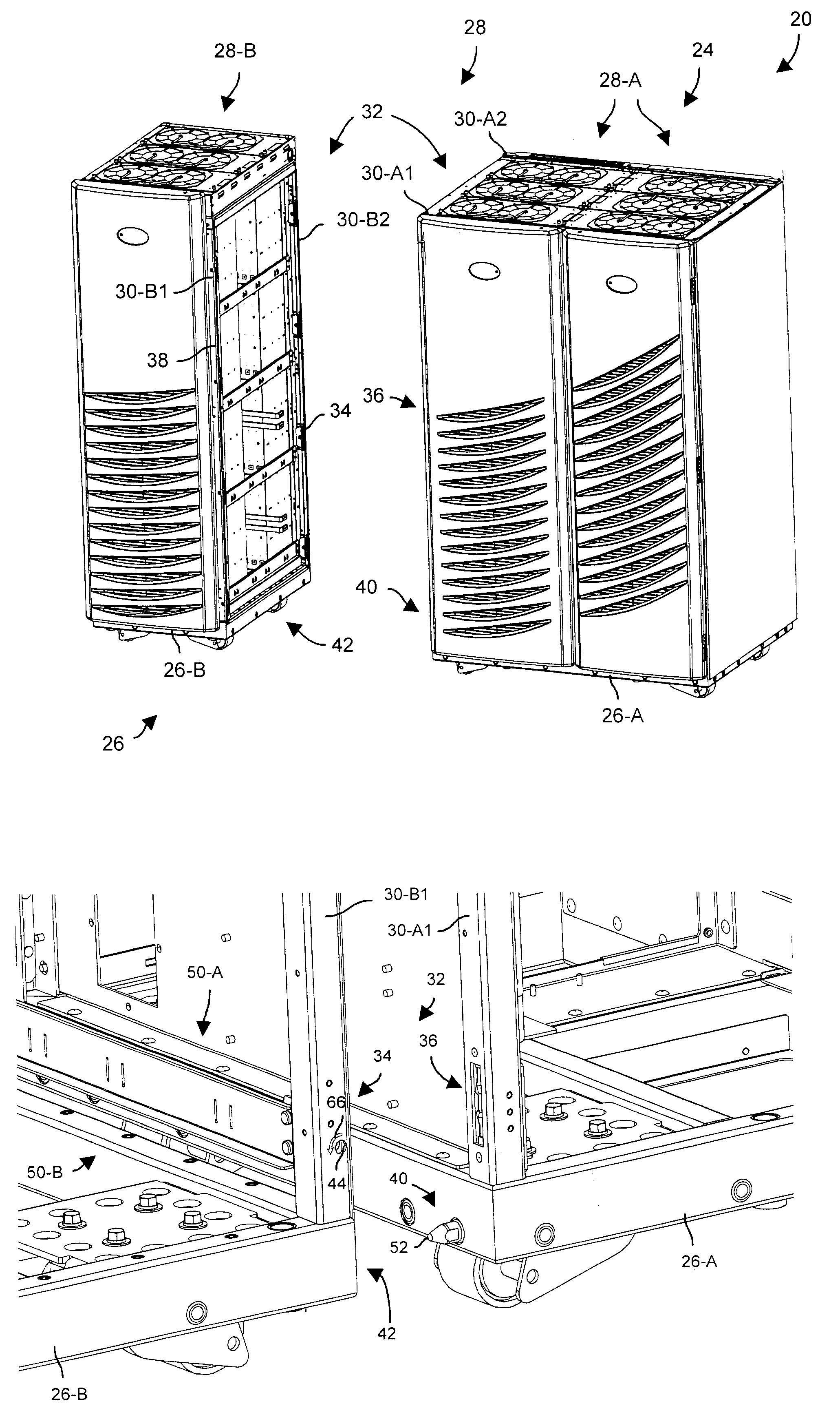
[0021]The invention is directed to techniques for interconnecting electronic cabinet frames using a set of latch subassemblies. Such subassemblies provide a user (e.g., a manufacturer, a customer, etc.) with flexibility to selectively interconnect and disconnect electronic cabinet frames without handling any nuts or bolts. Accordingly, the user has the capability to subsequently separate the electronic cabinet frames to accommodate certain situations (e.g., narrow facilities at an installation location, a reduced demand for large-scale configurations, etc.) as well as to avoid the risks associated with handling loose hardware (e.g., to avoid loosing nuts and bolts during shipping, dropping a nut or a bolt into electronic circuitry, etc.).

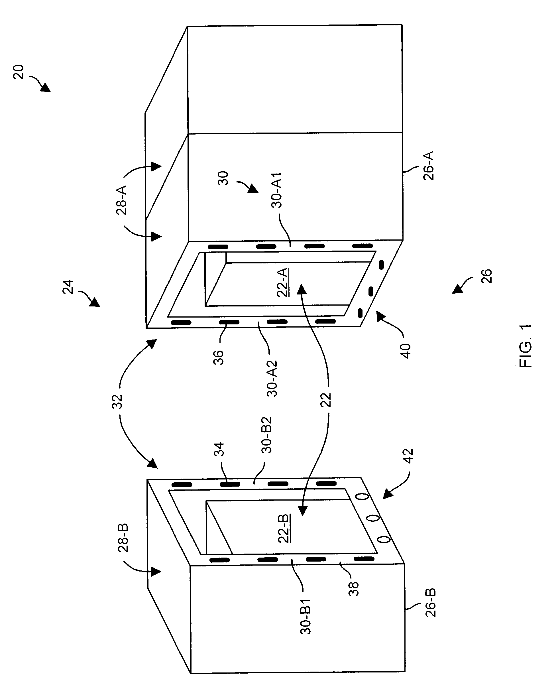
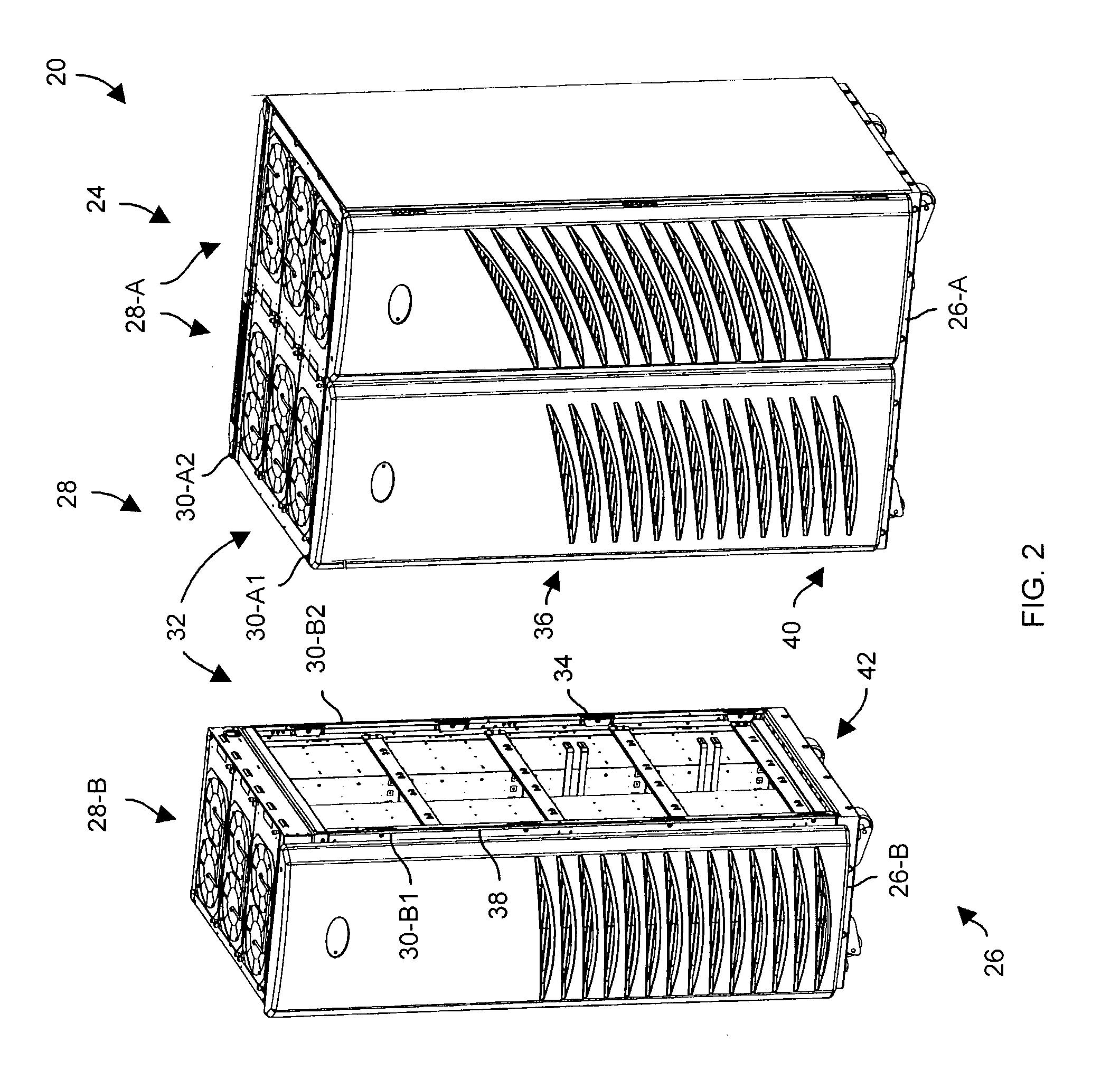
[0022]FIGS. 1–3 show an electronic system 20 which is suitable for use by the invention. FIG. 1 is a general block diagram of the electronic system 20 in an unconnected state. FIG. 2 is a perspective view of the electronic system 20 in the unconnect...


PUM


Abstract

An electronic system has electronic equipment (e.g., data storage equipment), and an electronic cabinet assembly which is configured to support the electronic equipment. The electronic cabinet assembly includes a first electronic cabinet frame defining a first set of electronic equipment bays to carry a first portion of the electronic equipment, and a second electronic cabinet frame defining a second set of electronic equipment bays to carry a second portion of the electronic equipment. The electronic cabinet assembly further includes a set of latch subassemblies which is configured to selectively (i) interconnect the first and second electronic cabinet frames, and (ii) disconnect the first and second electronic cabinet frames from each other. Accordingly, a user is capable of conveniently attaching the electronic cabinet frames together using the set of latch subassemblies, and optionally separating the electronic cabinet frames at a later time, without handling any nuts or bolts.

Description

BACKGROUND OF THE INVENTION[0001]A typical electronic cabinet has a frame, a set of wheels that support the frame over a floor surface, and a set of panels that mount over the frame. Such a cabinet is generally well-suited for housing electronic circuitry such as a general purpose computer, network hardware, specialized equipment, etc. In particular, the wheels enable a user to conveniently move the electronic circuitry from one location to another (e.g., the wheels enable the user to roll the cabinet across a computer room floor during installation or relocation of the electronic circuitry). Furthermore, the set of panels (e.g., doors, side members, etc.) protect the electronic circuitry against damage (e.g., prevents external objects or bystanders from inadvertently contacting the electronic circuitry, discourages tampering, etc.).[0002]Equipment manufacturers often provide electronic cabinets in standard sizes. That is, manufacturers typically provide frames having horizontal and...

Claims


Application Information

Patent Timeline
Patent Type & Authority Patents(United States)
IPC IPC(8): A47B97/00A47B87/00H05K5/00
CPCA47B87/008H05K5/0021H05K7/1488
Inventor NELSON, ERIK C.CASTRO, FERNANDO LUIS
Owner EMC IP HLDG CO LLC
Why Eureka
Try Eureka