Gyratory crusher spider arm shield

Active Publication Date: 2016-01-21
SANDVIK INTELLECTUAL PROPERTY AB
View PDF0 Cites 5 Cited by
  • Summary
  • Abstract
  • Description
  • Claims
  • Application Information

AI Technical Summary

Benefits of technology

[0005]It is an objective of the present invention to provide a shield or guard for a spider arm that may be conveniently attached and dismounted from the spider assembly without compromising the physical and mechanical integrity

Problems solved by technology

However, such configurations are disadvantageous as the bolt heads are exposed to the crushable material as it falls into the crushing chamber.
With use, the bolt heads become damaged leading to attachment failure a

Method used


Image

  • Gyratory crusher spider arm shield
  • Gyratory crusher spider arm shield
  • Gyratory crusher spider arm shield

Examples


Example

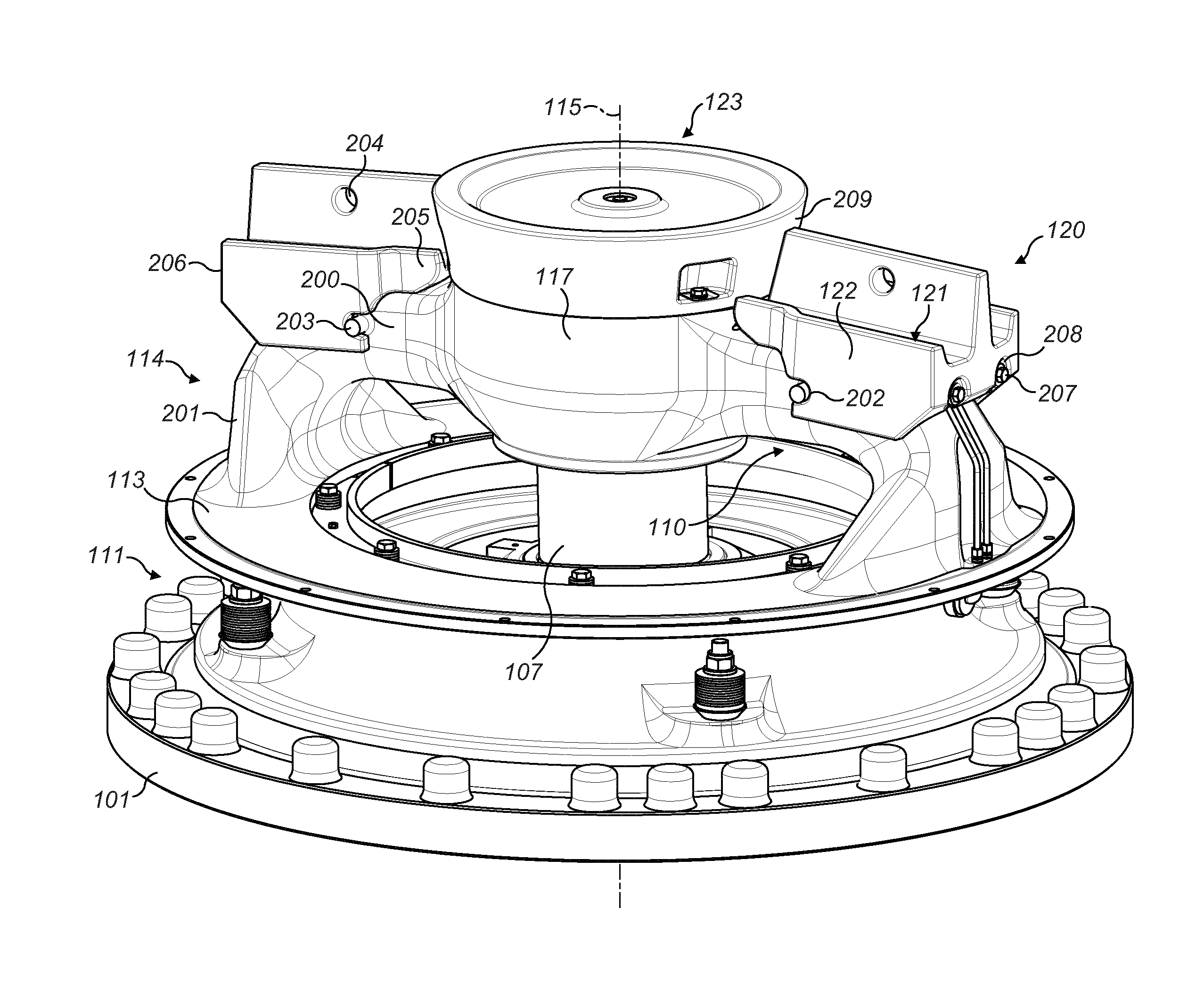
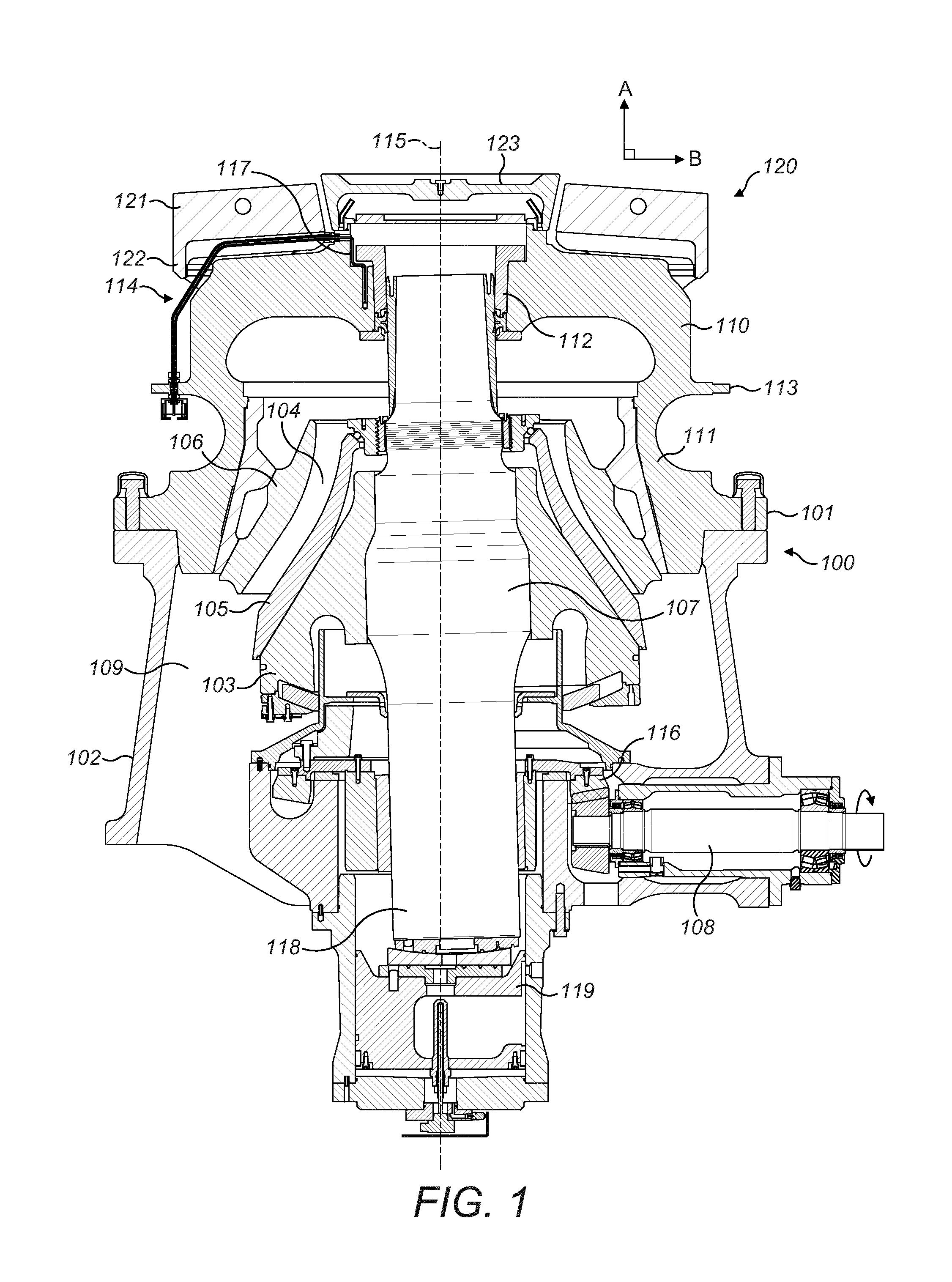
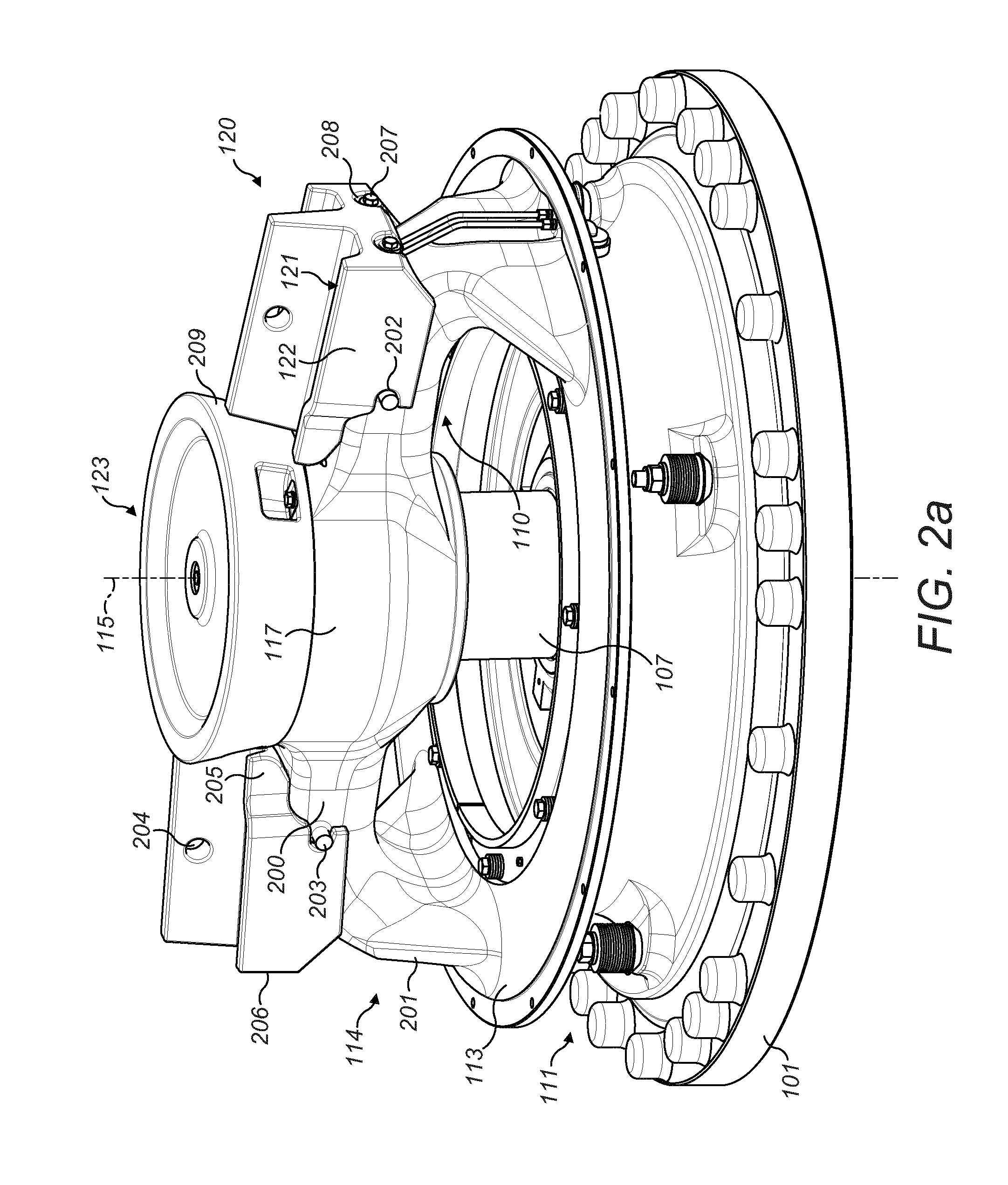
[0031]Referring to FIG. 1, a crusher comprises a frame 100 having an upper frame 101 and a lower frame 102. A crushing head 103 is mounted upon an elongate shaft 107. A first (inner) crushing shell 105 is fixably mounted on crushing head 103 and a second (outer) crushing shell 106 is fixably mounted at upper frame 101. A crushing zone 104 is formed between the opposed crushing shells 105, 106. A discharge zone 109 is positioned immediately below crushing zone 104 and is defined, in part, by lower frame 102.

[0032]A drive (not shown) is coupled to main shaft 107 via a drive shaft 108 and suitable gearing 116 so as to rotate shaft 107 eccentrically about longitudinal axis 115 and to cause head 103 to perform a gyratory pendulum movement and crush material introduced into crushing chamber 104. An upper end region of shaft 107 is maintained in an axially rotatable position by a top-end bearing assembly 112 positioned intermediate between main shaft 107 and a central boss 117. Similarly, ...


PUM


Abstract

A gyratory crusher spider arm shield is configured for releasable attachment to a spider arm. The shield includes a main body having an underside foot for engaging onto an upper region of the arm. The secure attachment is provided by cooperation between an attachment element that extends radially inward from an outermost end of the shield and a mount guide provided at sidewalls of the shield that extend laterally each side of the spider arm.

Description

FIELD OF INVENTION[0001]The present invention relates to a gyratory crusher spider arm shield and in particular, although not exclusively, to a shield configured for the convenient mounting and dismounting at the spider arm so as to protect the arm from material to be crushed as it falls into the crushing zone.BACKGROUND ART[0002]Gyratory crushers are used for crushing ore, mineral and rock material to smaller sizes. Typically, the crusher comprises a crushing head (referred to as a mantle) mounted upon an elongate main shaft. A first crushing shell is mounted on the crushing head and a second crushing shell is mounted on a frame such that the first and second crushing shells define together a crushing chamber through which the material to be crushed is passed. A driving device positioned at a lower region of the main shaft is configured to rotate an eccentric assembly positioned about the shaft to cause the crushing head to perform a gyratory pendulum movement and crush the materia...

Claims


Application Information

Patent Timeline
IPC IPC(8): B02C2/06
CPCB02C2/06B02C2/045
Inventor BERGMAN, AXELERIKSSON, BENGT-ARNELARSSON, MIKAEL M.MALMQVIST, PATRIC
Owner SANDVIK INTELLECTUAL PROPERTY AB
Why Eureka
Try Eureka