Pump assembly

Active Publication Date: 2011-09-15
GRUNDFOS MANAGEMENT AS
View PDF6 Cites 9 Cited by
  • Summary
  • Abstract
  • Description
  • Claims
  • Application Information

AI Technical Summary

Benefits of technology

[0005]It is the object of the present invention to provide a pump assembly which has an improved mounting, which has a minimised number of individual parts, is easier to assemble, and furthermore permits an improved lubrication or cooling.

Problems solved by technology

The problem with this mounting is the bearing may often not be adequately cooled or lubricated.
Furthermore, with multi-stage pumps, it is a problem that the tolerances in each pump stage sum, so that on assembly, it is necessary to position the pump impellers relative to the rotor shaft, or to provide an axial compensation in the coupling between the drive motor and the rotor shaft.

Method used


Image

  • Pump assembly
  • Pump assembly
  • Pump assembly

Examples


Embodiment Construction

[0031]Certain terminology is used in the following description for convenience only and is not limiting. The words “inwardly” and “outwardly” refer to directions toward and away from, respectively, the geometric center of the device, and designated parts thereof, in accordance with the present invention. Unless specifically set forth herein, the terms “a,”“an” and “the” are not limited to one element, but instead should be read as meaning “at least one.” The terminology includes the words noted above, derivatives thereof and words of similar import.

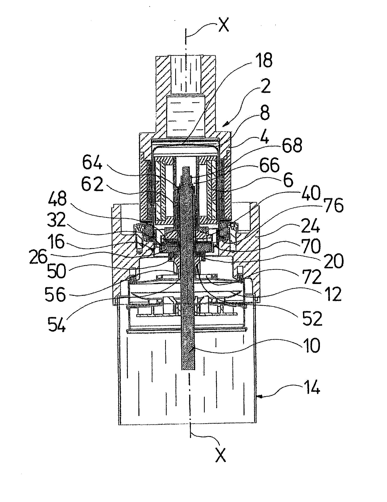
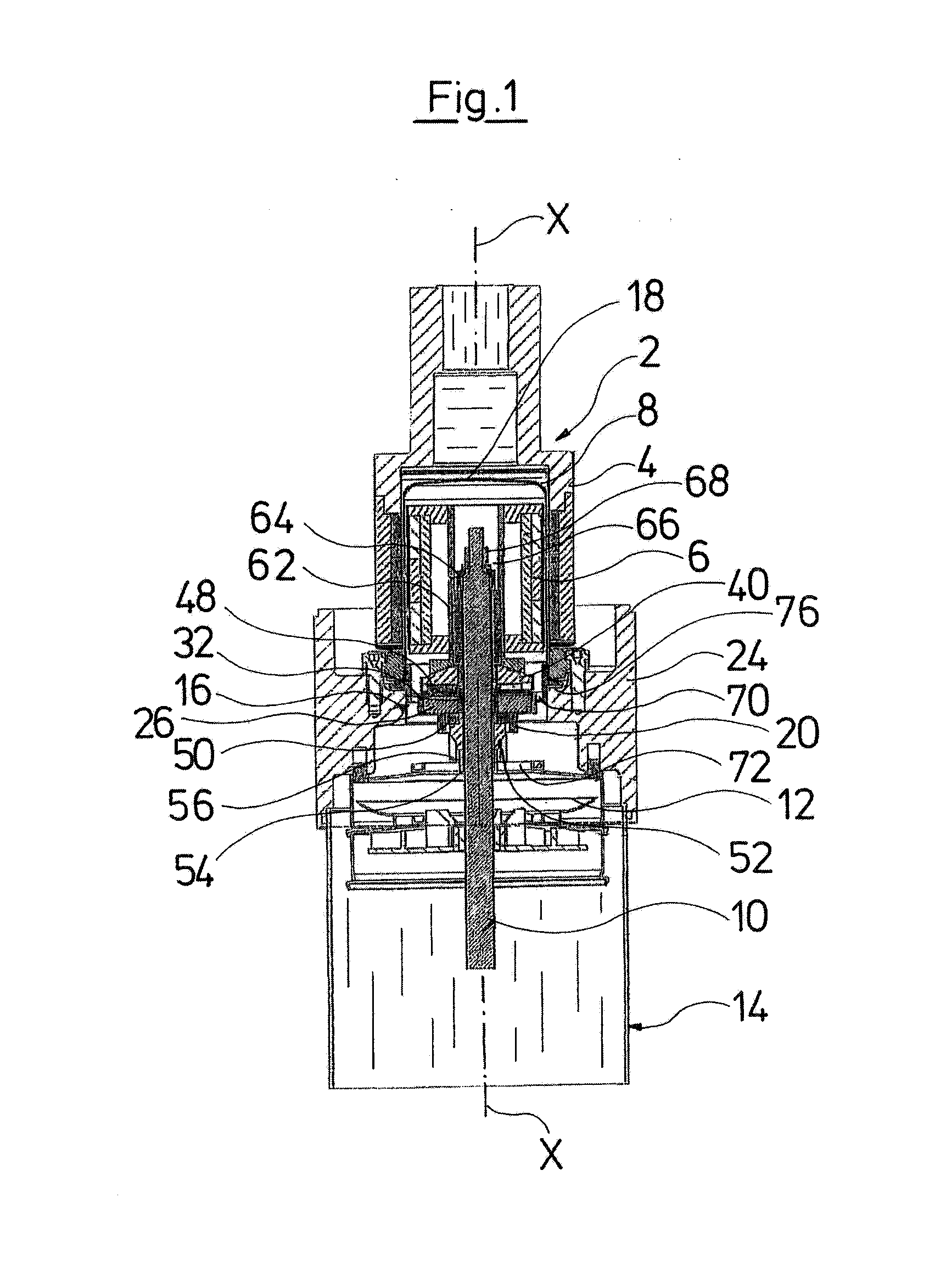
[0032]Referring to the drawings in detail, wherein like numerals indicate like elements throughout the several views, FIGS. 1-3 show a pump assembly according to a preferred embodiment of the present invention. The pump assembly preferably comprises a drive device 2 in the form of a magnet coupling. The magnet coupling preferably comprises an outer part 4 as well as an inner part 6, between which a can or a canned pot 8 is arranged. The o...


PUM


Abstract

A pump assembly with a rotatable rotor shaft (10), wherein the rotor shaft (10) includes at least one axial bearing (36, 40) and a radial bearing (30, 32), which are integrated into a common bearing assembly (16).

Description

CROSS-REFERENCE TO RELATED APPLICATIONS[0001]This application is a Section 371 of International Application No. PCT / EP2008 / 008839, filed Oct. 18, 2008, which was published in the German language on May 7, 2009, under International Publication No. WO 2009 / 056242 A1 and the disclosure of which is incorporated herein by reference.BACKGROUND OF THE INVENTION[0002]The present invention relates to a pump assembly, and in particular to a bearing arrangement in a pump assembly.[0003]Pump assemblies usually comprise a drive device, for example an electric motor, a rotor shaft and an impeller arranged thereon. The rotor shaft thereby, must be mounted in the axial and radial direction. In particular, the pressure forces acting on the impeller on operation of the pump must be accommodated in the axial direction. For this, with regard to pumps with canned motors or magnet couplings with cans in the drive unit, usually a bearing is arranged at the axial end of the rotor shaft in the can. The prob...

Claims


Application Information

Patent Timeline
IPC IPC(8): F01D25/16
CPCF04D29/0462F16C17/26F16C17/10F04D29/0473
Inventor GRANN, HELGEPEDERSEN, ALFRED LISBJERG
Owner GRUNDFOS MANAGEMENT AS
Why Eureka
Try Eureka