Connection of a flanged ring of a hub bearing unit to a motor vehicle wheel or suspension standard of a motor vehicle

a technology of a hub bearing unit and a flange is applied in the direction of threaded fasteners, bearing unit rigid support, screw, etc., which can solve the problems of increasing production costs, insufficient connection of screws to the hub flange, and high stress on small surface areas, so as to improve the mounting and locking of the hub bearing unit, improve the stability and precision of threaded connection, and simplify the positioning of the threaded elements

Active Publication Date: 2014-11-25
AB SKF
View PDF14 Cites 1 Cited by
  • Summary
  • Abstract
  • Description
  • Claims
  • Application Information

AI Technical Summary

Benefits of technology

[0012]A general object of the invention is to improve the mounting and locking of a hub bearing unit having a flange of light material onto a wheel or onto a standard of the suspension. More specifically, an object is to provide a stable and precise threaded connection, to simplify the positioning of the threaded elements for fastening to the wheel or to the standard, and to optimize the distribution of stresses in the flange. Another object is to prevent the rotation of the threaded fixing elements with respect to the flange in the course of tightening and unscrewing.

Problems solved by technology

This causes a concentration of high stresses on small surface areas.
If axial knurling is provided on the screws, the connection of the screws to the hub flange is found to be insufficiently strong if the material of the flange is less hard than steel, or if the material of the flange has a higher coefficient of thermal expansion than the fastening screw.
However, this requires special machining operations on the flange and screws in order to create a specific shape, which increases production costs.
In the latter case, the flow of plastic material in the moulding cavity is not sufficient to ensure the good structural quality of the portions of the flange located around the insert.
In particular, an imperfect flow of plastic material causes incomplete filling of the areas downstream of the inserts, with respect to the direction of the flow of material in the mould.
Self-tapping inserts and the operations for their insertion require considerable expenditure.

Method used


Image

  • Connection of a flanged ring of a hub bearing unit to a motor vehicle wheel or suspension standard of a motor vehicle
  • Connection of a flanged ring of a hub bearing unit to a motor vehicle wheel or suspension standard of a motor vehicle
  • Connection of a flanged ring of a hub bearing unit to a motor vehicle wheel or suspension standard of a motor vehicle

Examples


Embodiment Construction

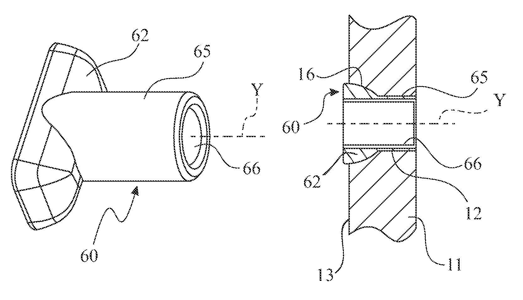
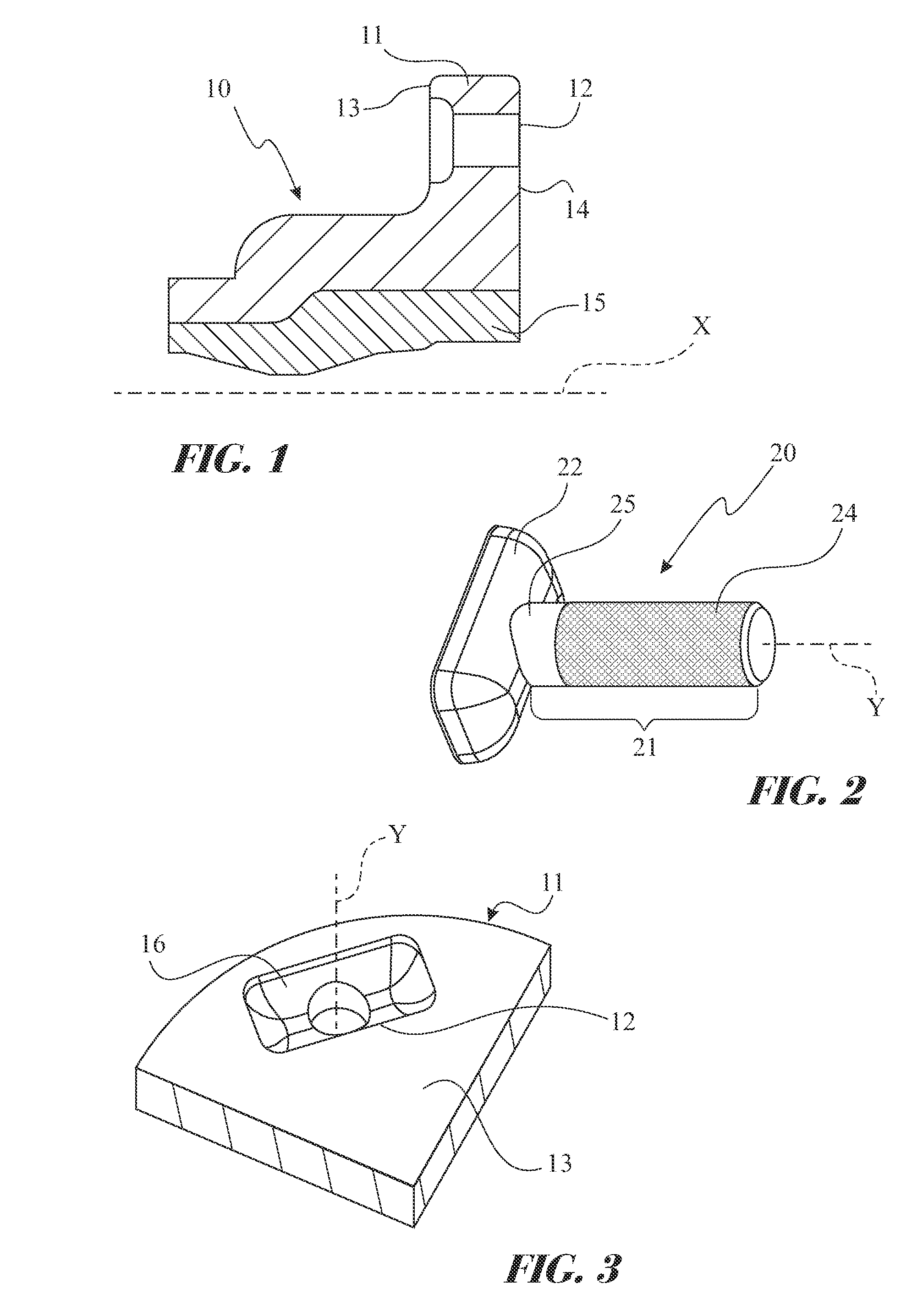
[0025]With initial reference to FIG. 1, the number10 indicates a flanged ring forming part of a hub-bearing unit (not shown). The ring 10 defines a central axis of rotation X and is designed to be used either as the rotatable ring which is connected to the vehicle wheel, or as the stationary ring which is connected to the suspension standard. For this connection, the ring 10 is provided with a flange 11, which extends in a radially outward direction and has four or five parallel axial through bores 12 formed in it at angularly equally spaced positions around the axis X.

[0026]Throughout the present description and the claims, any terms and expressions indicating positions and directions, such as “radial” and “axial”, are to be understood as referring to the axis of rotation X of the hub-bearing unit. On the other hand, expressions such as “axially inner” (or “inboard”) and “axially outer” (or “outboard”) refer to the mounted condition on the vehicle. In the following description, ref...


PUM


Abstract

A hub bearing assembly for a motor vehicle wheel comprises a flanged ring and a set of pin connection elements. The flanged ring defines a central axis of rotation and comprises a tubular core made of steel and an outer flange of light metallic material having axial bores formed therethrough. Each pin connection element includes a head portion and an axial cylindrical shank defining a respective longitudinal axis parallel to the axis of rotation and is accommodated in one of the bores, and a threaded cylindrical surface for connecting the flanged ring to a wheel or to a suspension standard of the vehicle. Each head portion is shaped differently from that of a solid of revolution generated about the longitudinal axis of the shank portion. Each head portion is accommodated in a respective recess of corresponding shape, formed in one of the two radial opposite faces of the flange.

Description

CROSS-REFERENCE TO RELATED APPLICATION[0001]This United States Non-Provisional Utility application claims the benefit of co-pending Italian Patent Application Serial No. TO2010A00105, filed on 27 Dec. 2010, which is incorporated herein in its entirety.FIELD OF THE INVENTION[0002]The present invention relates to a connecting element for connecting a flanged ring of a hub-bearing unit to a wheel or a suspension standard of a motor vehicle. The invention further relates to a hub bearing assembly comprising the said connecting element.BACKGROUND OF THE INVENTION[0003]In order to mount a wheel on the hub of a motor vehicle, bolted connections are conventionally used. In the procedures most commonly used at the present time, threaded bores are conventionally provided in the flange of the hub and through bores are formed in the wheel for the purpose of fixing the wheel to the radial flange of the hub; the wheel, a flange of the brake rotor and the radial flange of the hub are placed axiall...

Claims


Application Information

Patent Timeline
Patent Type & Authority Patents(United States)
IPC IPC(8): F16C33/60B60B27/00
CPCB60B27/0005B60B27/001Y02T10/86F16C33/60F16C35/06F16B35/06F16C19/386F16C33/581F16B37/00B60B3/16B60B27/00B60B27/0047F16C2326/02
Inventor KNOPF, ANDREASRE, PAOLO
Owner AB SKF
Why Eureka
Try Eureka