Bearing assembly with integrated generator

Inactive Publication Date: 2016-05-05
AB SKF
View PDF11 Cites 5 Cited by
  • Summary
  • Abstract
  • Description
  • Claims
  • Application Information

AI Technical Summary

Benefits of technology

[0018]During operation, a magnetic coupling is formed between the magnetic rotor and the target surface of the saddle adapter, which drives the rotor into rotation. When the revolving end cap is in an angular position where the magnetic rotor is no longer overlapped by the saddle adapter, the rotor's momentum keeps it rotating until it is once again “driven” by the magnetic fields generated by the eddy currents which are induced in the target surface. Thus, continuous power generation is possible even when the target surface is not formed by a continuous circle.
[0019]In a bearing assembly according to the invention, the target surface may be a surface of the second part. In the embodiment described above, where the bearing assembly is a railway journal bearing, the saddle adapter, comprising the target surface, is typically made of steel. In other embodiments, where the second part is one of the bearing rings, the target surface is made of bearing steel. When the second part is a shield or seal, the target surface may be an annular surface of a casing element that is made of e.g. steel. By using a surface of one of the parts of the bearing assembly as the target surface, the number of components of the assembly i

Problems solved by technology

The oppositely polled magnetic fields act on the magnets of the magneti

Method used


Image

  • Bearing assembly with integrated generator
  • Bearing assembly with integrated generator
  • Bearing assembly with integrated generator

Examples


Example

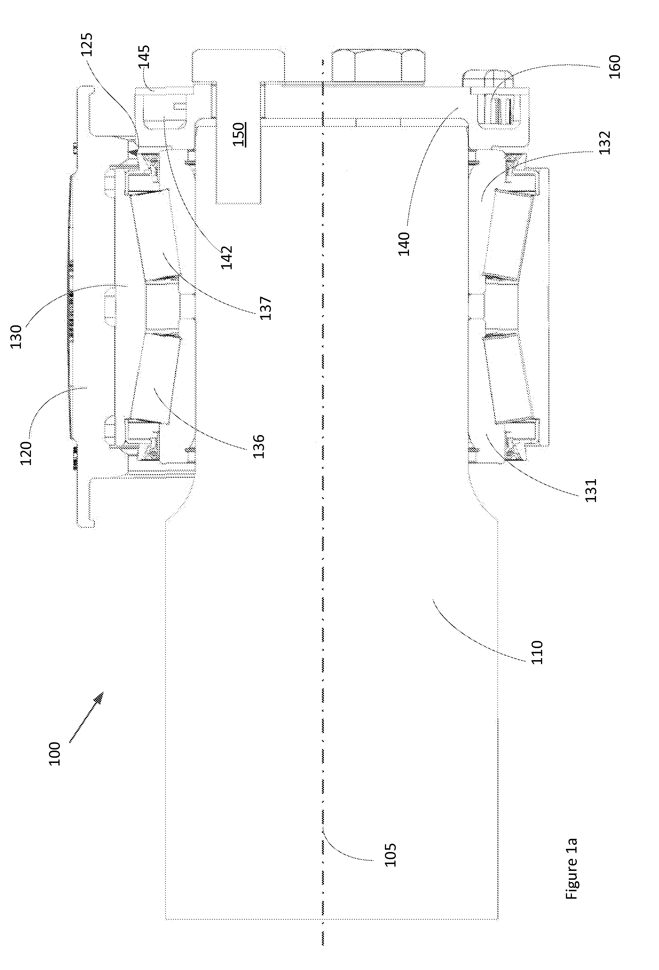
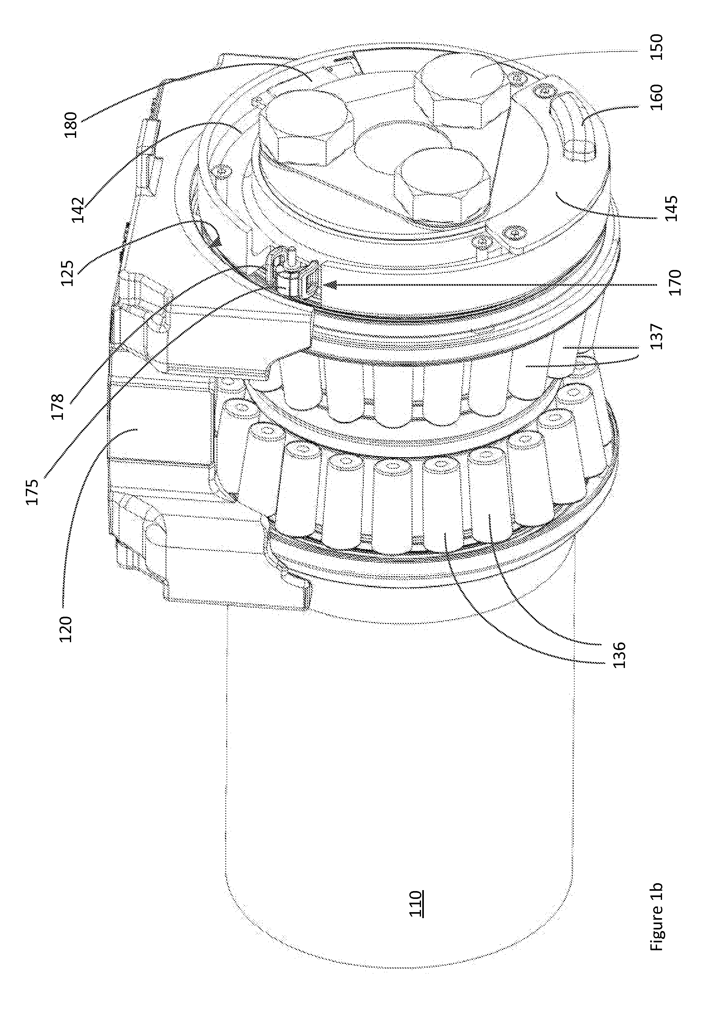
[0036]An embodiment of a bearing assembly according the invention is shown in FIGS. 1a and 1b. The assembly 100 comprises a double-row tapered roller bearing which supports a railway axle 110 relative to a housing 120, which housing is typically referred to as a saddle adapter. The bearing comprises an outer ring 130 (hidden from view in FIG. 1b), mounted to the saddle adapted 120, and further comprises first and second inner rings 131, 132 for accommodating first and second rows of tapered rollers 136, 137. The bearing is preloaded via an end cap 140, which bears against an axially outer face of the second inner ring 132 and is bolted to the axle 110 via three bolts 150.

[0037]The end cap 140 comprises an annular cavity 142 in which a sensor unit 160 is housed. The sensor unit comprises at least one sensor for measuring a parameter which is indicative of an operating condition of the bearing. In the depicted example, the sensor unit comprises a vibration sensor. The sensor unit may ...


PUM


Abstract

A bearing assembly comprising a generator for harvesting electrical energy from rotational kinetic energy. The electromagnetic induction generator includes a magnetic rotor (including a plurality of magnets arranged with alternating polarities along a rotor periphery) and a stator having a coil. The generator is mounted to a first part of the assembly, which is rotatable about the bearing axis of rotation. The magnetic rotor is rotationally supported relative to the stator and is rotatable about an axis of rotation, which is different from the bearing axis of rotation. The assembly further comprises a target surface made of an electrically conductive material provided on a second part of the bearing assembly. During operation, relative rotation takes place between the first and second parts. The rotor is arranged whereby magnetic field lines from the plurality of magnets intersect the target surface during at least part of one revolution about the bearing axis.

Description

CROSS REFERENCE TO RELATED APPLICATION[0001]This is a Non-Provisional Patent Application, filed under the Paris Convention, claiming the benefit of Great Britain (GB) Patent Application Number 1419220.7, filed on 29 Oct. 2014 (29.10.2014), which is incorporated herein by reference in its entirety.FIELD OF THE INVENTION[0002]The invention relates to a bearing assembly comprising a rolling element bearing and means for generating electrical energy from rotation of the assembly.BACKGROUND TO THE INVENTION[0003]An example of such a bearing assembly is disclosed in EP 1292831. The assembly comprises a wireless self-powered sensor unit which is electrically powered by an integrated generator. Electric power is generated via electromechanical energy conversion using permanent magnets, an armature winding and a target wheel that is mounted to and rotates with one of the bearing rings. In one example, the generator comprises a stator formed by a winding that encircles a magnetic core, whereb...

Claims


Application Information

Patent Timeline
IPC IPC(8): H02K7/18F16C19/38F16C41/00
CPCH02K7/1846F16C19/386F16C41/004B61F15/12B61K9/04F16C35/063F16C19/52H02K49/106H02K16/00B61F15/26F16C2326/10H02K49/10F16C19/385
Inventor ANGELIS, GEORGOMEULEMAN, PETER KLEIN
Owner AB SKF
Why Eureka
Try Eureka