
Intraocular lens injector subassembly

a technology of injectors and sub-assemblies, which is applied in the field of preloaded injector sub-assemblies, can solve problems such as trauma to the surrounding tissues of the eye, and achieve the effect of facilitating the loading of an injector

Inactive Publication Date: 2008-06-26
BAUSCH & LOMB INC
View PDF99 Cites 19 Cited by
  • Summary
  • Abstract
  • Description
  • Claims
  • Application Information

AI Technical Summary

Benefits of technology

[0012]Another aspect of the invention is directed to a method for facilitating loading of an IOL injector, comprising providing an IOL injector subassembly, the subassembly comprising (I) a lens cartridge comprising (i.) a first portion comprising a first lumen segment, and (ii.) a second portion comprising a second lumen segment, the second portion being rotatably connected to the first portion. The subassembly also comprises an IOL, and a fastener connected to the lens cartridge arranged to hold the IOL in a position disposed over at least a portion of the first lumen segment and over at least the second lumen segment. The method also comprises removing the fastener; and rotating the first portion relative to the second portion to fold the IOL.

Problems solved by technology

Should an IOL be damaged or expelled from the injector in an incorrect orientation, a surgeon may need to remove or further manipulate the IOL in the eye, possibly resulting in trauma to the surrounding tissues of the eye.

Method used


Image

  • Intraocular lens injector subassembly
  • Intraocular lens injector subassembly
  • Intraocular lens injector subassembly

Examples


Embodiment Construction

[0028]Aspects of the present invention are directed towards an IOL injector subassembly comprising a lens cartridge and a fastener connected to the cartridge arranged to maintain an IOL on the cartridge. In some embodiments, the subassembly is configured to facilitate loading of an IOL injector with an IOL by limiting the manipulation of the subassembly by surgical staff to: (1) removal of the fastener, (2) closing of the cartridge to fold the IOL, and (3) connection of the cartridge with remaining components of an injector. According to some embodiments, all of the steps may be accomplished without surgical staff directly contacting the IOL.

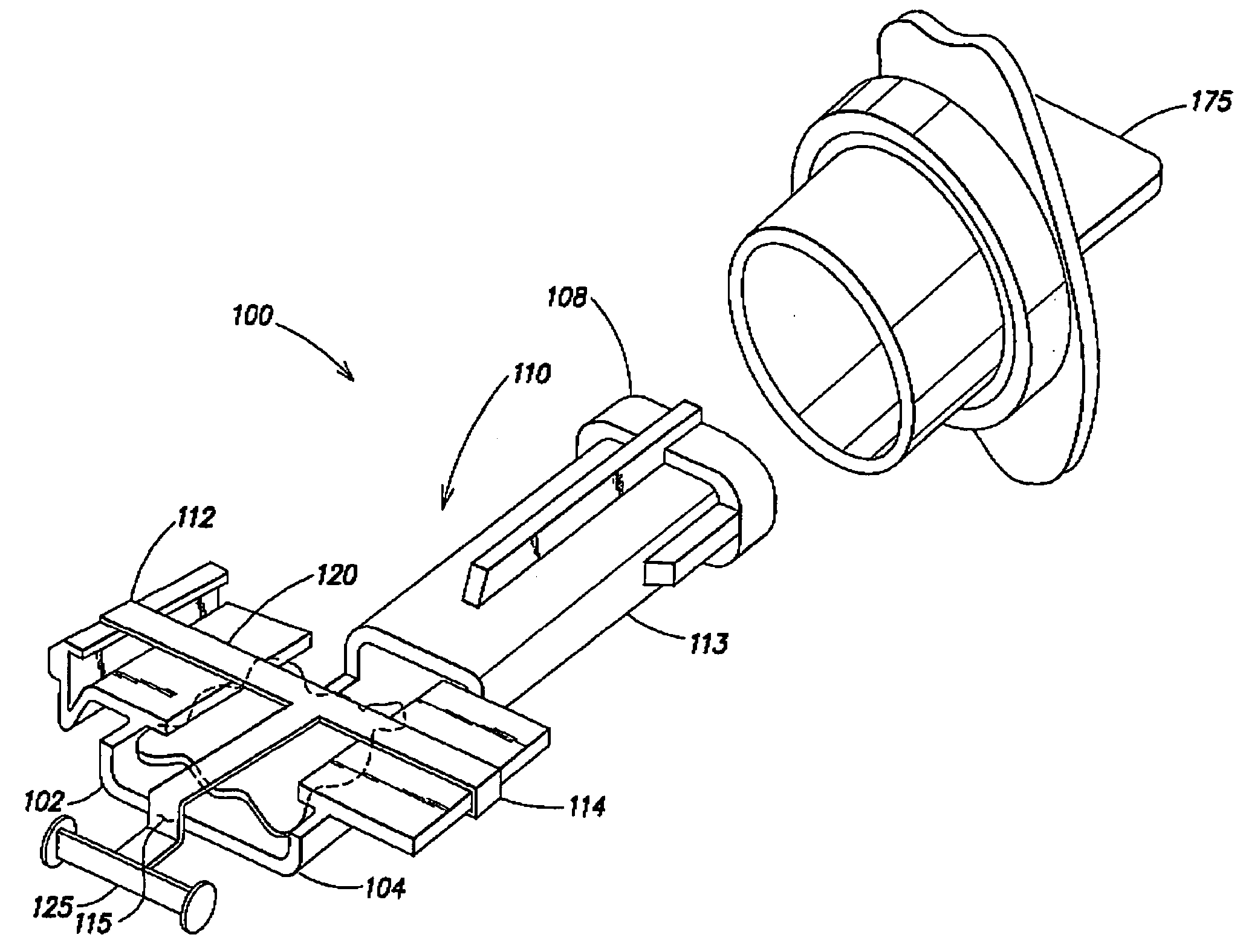
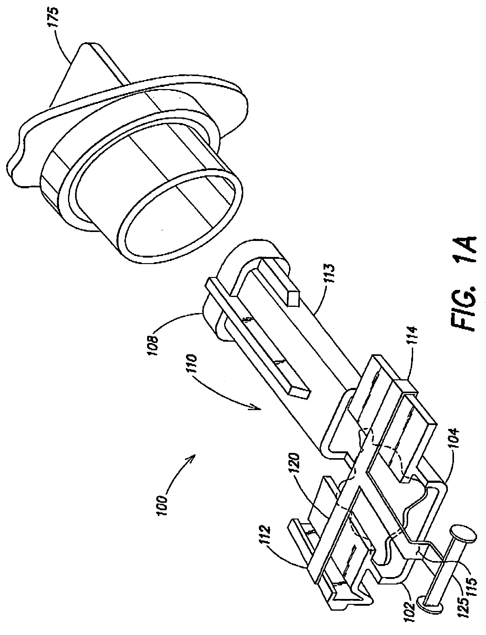
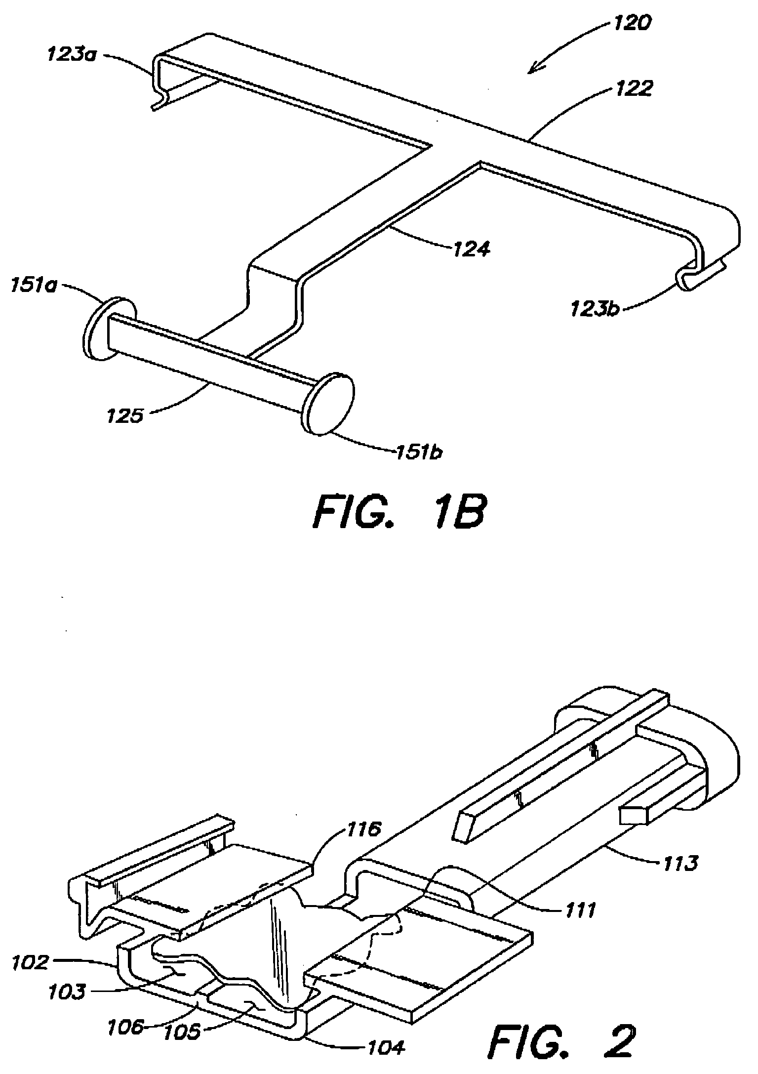
[0029]FIG. 1A is a perspective view of an example of an embodiment of an IOL injector subassembly 100 according to aspects of the invention. The subassembly comprises a lens cartridge 110 and a fastener 120 connected to the lens cartridge configured and arranged to hold an IOL 150 on the cartridge, and to maintain the cartridge in an open state....


PUM


Abstract

An IOL injector subassembly, comprising a lens cartridge, an IOL, and a fastener connected to the lens cartridge arranged to hold the IOL in a position disposed over at least a portion of the first lumen segment and over at least the second lumen segment. A method for facilitating loading of an IOL injector, comprising removing the fastener, and rotating the first portion relative to the second portion to fold the IOL.

Description

FIELD OF THE INVENTION[0001]The present invention relates to intraocular lens injector subassemblies, and more particularly to preloaded injector subassemblies.BACKGROUND OF THE INVENTION[0002]IOLs are artificial lenses used to replace natural crystalline lenses of patients' when their natural lenses are diseased or otherwise impaired. Under some circumstances a natural lens may remain in a patient's eye together with an implanted IOL. IOLs may be placed in either the posterior chamber or the anterior chamber of an eye.[0003]IOLs come in a variety of configurations and materials. Various instruments and methods for implanting such IOLs in an eye are known. Typically, an incision is made in a patient's cornea and an IOL is inserted into the eye through the incision. In one technique, a surgeon uses surgical forceps to grasp the IOL and insert it through the incision into the eye. While this technique is still practiced today, more and more surgeons are using IOL injectors, which offe...

Claims


Application Information

Patent Timeline
Patent Type & Authority Applications(United States)
IPC IPC(8): A61F2/06
CPCA61F2/1691A61F2/1664
Inventor PYNSON, JOELRATHERT, BRIAN D.POLLOCK, DAVID P.
Owner BAUSCH & LOMB INC
Learn More