Hand-held cutting device

a cutting device and hand-held technology, applied in the direction of metal-working hand tools, metal-working tools, manufacturing tools, etc., can solve the problems of poor device efficiency, difficult disassembly of blades, and complex design of moving parts, etc., and achieve the effect of reducing the risk of operator injuries

Active Publication Date: 2008-07-03
ES EQUIP HLDG
View PDF17 Cites 17 Cited by
  • Summary
  • Abstract
  • Description
  • Claims
  • Application Information

AI Technical Summary

Benefits of technology

[0010]Another object of the invention is to provide a cutting device making it possible to shift to a new edge on the same cutting element without tools and without dismounting the cutting element from the cutting head which reduces the risk of injuries to the operator and damages to the cutting element itself.
[0011]A further object is to provide a cutting device making it possible to replace the cutting element without tools.
[0014]A still further object is to provide a cutting device making it possible to change the type, especially the form (polygonal) of the cutting element without making other changes to the cutting device.
[0016]A still further object is to provide a cutting device eliminating the risk of clogging during the cutting procedure.
[0017]A still further object is to provide a cutting device presenting an active cutting edge having an instantaneous decrease of the cutting angle in the feeding direction increasing the cutting efficiency for certain materials.

Problems solved by technology

One of the disadvantages of this holder is that the blade has to be dismounted when shifting to a new edge on the same blade.
The disadvantages of this device of the same as listed above.
An essential disadvantage with this device is of course the complicated design with several moving elements and adjustment needs.
Additionally, the efficiency of the device is poor due to the rotating movement of the cutting element.

Method used


Image

  • Hand-held cutting device
  • Hand-held cutting device
  • Hand-held cutting device

Examples


Embodiment Construction

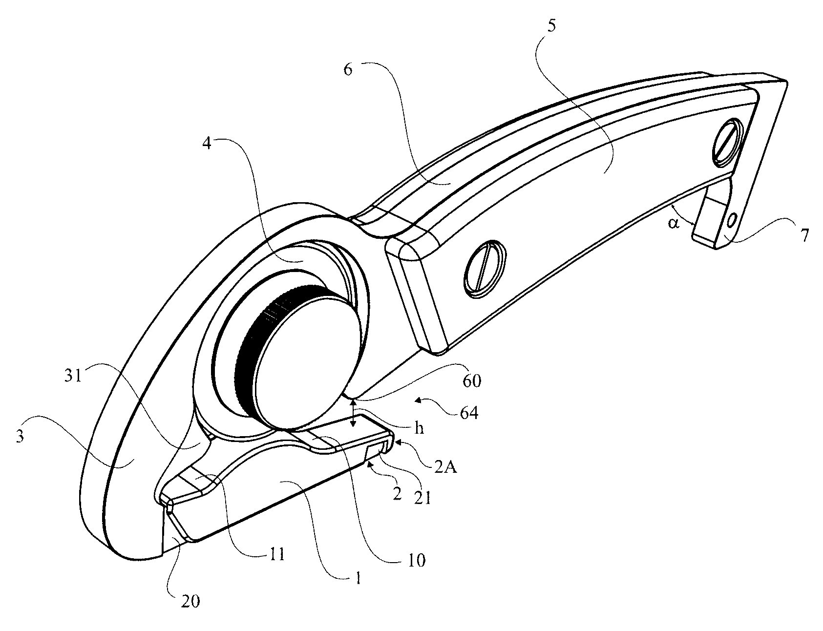
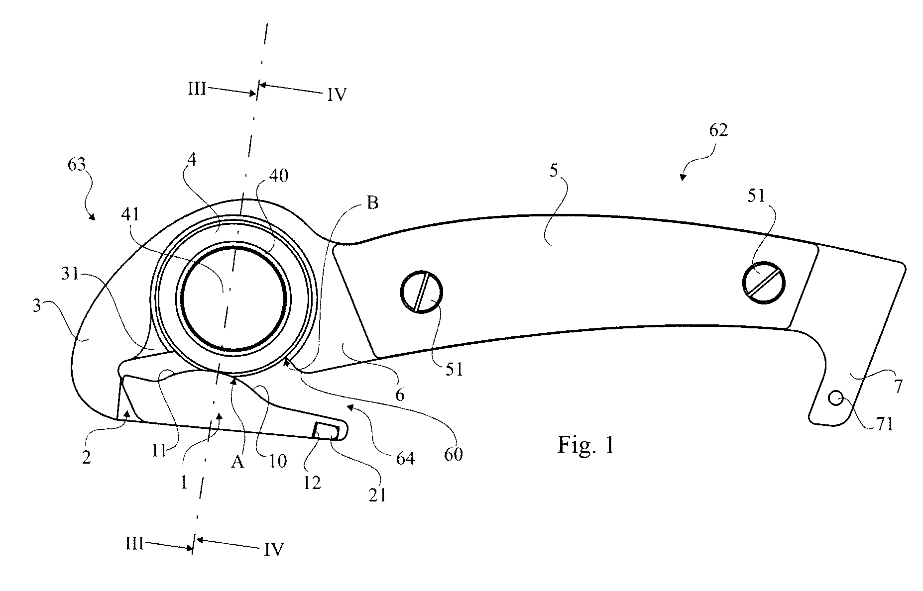
[0028]FIG. 1 shows a side view of an embodiment of the cutting device according to the invention.

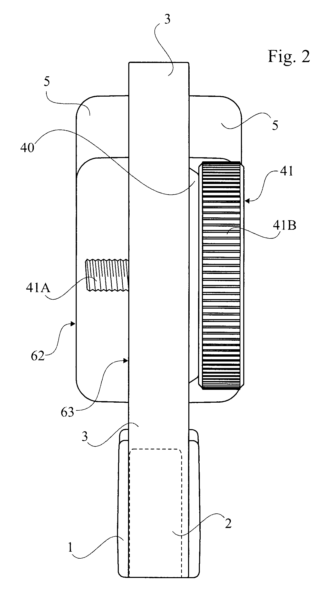
[0029]The cutting device according to the invention comprises a main body 6 which is more clearly shown in FIG. 7 integrating a handle 62 and a cutting head 63 extending from the front end of the handle. At the rear end of the handle a glide stop 7 is arranged for making the grip more secure when pulling. The main body has to be made of a strong rigid material such as aluminium, brass, steel, plastic, especially reinforced plastic like e.g. carbon reinforced plastic resin or the like. In one embodiment the main body 6 has been machined in a piece of aluminium. As can be seen from the figures the handle has been given a somewhat curved form which together with the protruding glide stop 7 (preferably forming a sharp angle a in relation to the extension of the main body 6) together with handle covers 5, cf. FIG. 7, fixed on each side of the main body results in a ergonomic design especially...


PUM


Abstract

This invention relates to a hand held cutting device, comprising a handle (62) and a cutting head (63), a cutting element (4) attached to said cutting head (63), a guiding and supporting element (2) extending from said cutting head (63), said guiding and supporting element (2) and cutting head (63) arranged to form a protecting periphery such that any part of a cutting edge (4A) of said cutting element (4) does not protrude outside of said periphery, said guiding and supporting element (2) including a distal portion (2A) arranged to form a feed channel (64) together with a portion (60) of said handle (62) and a support device (1) arranged on said guiding and supporting element (2), which support device (1) is arranged to interact with said cutting edge (4A) to improve cut ability, wherein said cutting element (4) is arranged to be none rotate ably, fixedly attached to said cutting head (63), by means of a locking device (40, 41) that provides for at least three different re-positioning and thereby renewing of said cutting edge (4a).

Description

TECHNICAL FIELD[0001]This invention relates to a hand held cutting device, more particularly, to a cutting device especially adapted for cutting textile type of material e.g. clothes.[0002]In accident situations with a suspected injury it could be very important to liberate a victim of the accident from his clothes for diagnosis purposes or instantaneous treatment. Additionally, when there is e.g. exposure to dangerous chemicals it could also be very important to liberate the victim from his clothes if they have been soaked with such chemicals.[0003]The device according to the invention could of course be used in other situations and for cutting e.g. rugs, carpets, mats, and other fabrics and work pieces as well. A particular use is for quickly removing e.g. tape and bandages used in the sport environment. Another use is for rapid severing of a safety or seat belt of a motor vehicle to release a passenger there from in the event of an emergency.BACKGROUND ART[0004]Cutting devices fo...

Claims


Application Information

Patent Timeline
Patent Type & Authority Applications(United States)
IPC IPC(8): B26B29/02
CPCB26B25/005B26B5/00
Inventor BERGSTRAND, MARTIN
Owner ES EQUIP HLDG
Why Eureka
Try Eureka