Water reservoir pressure vessel

a pressure vessel and water reservoir technology, applied in the field of pressure vessel, can solve the problems of increasing the amount and length of water lines within the refrigerator, unsightly and unwanted water stains on and around the exterior dispenser, and unwanted dripping of water from the exterior dispenser, so as to prevent bacterial growth

Active Publication Date: 2008-07-03
WHIRLPOOL CORP
View PDF21 Cites 48 Cited by
  • Summary
  • Abstract
  • Description
  • Claims
  • Application Information

AI Technical Summary

Benefits of technology

[0007]It is a further object, feature, or advantage of the present invention to provide a water reservoir pressure vessel wherein the vessel is constructed of a cross-linked, high-density polyethylene (HDPE) wherein the cross-inking is by beta irradiation.
[0008]Yet another object, feature, or advantage of the present invention is to provide a water reservoir pressure vessel for fitting behind the filter eject button of the filter disclosed in U.S. Pat. App. No. 2006 / 0081805.
[0009]A further object, feature, or advantage of the present invention is to provide a water reservoir pressure vessel resistant to fatigue related failures.
[0010]Yet another object, feature, or advantage of the present invention is to provide a water reservoir pressure vessel capable of being disposed in advance of the water filter and valves to keep chlorinated water in the vessel to prevent bacterial growth.
[0011]One or more of these and / or other objects, features, or advantages of the present invention will become apparent from the specification and claims that follow.
[0012]According to one aspect of the present invention, a water vessel for use with a refrigeration device having a water dispensing system to dispense water from a water supply line to an exterior water dispenser and / or an icemaker is disclosed. The water vessel is constructed having an inlet adapted to be in fluid communication with the water supply line and an outlet adapted to be in fluid communication with the exterior water dispenser. A plurality of pressure resistant walls are formed between the inlet and the outlet to create an internal volume to reservoir water. The water vessel is constructed to reservoir water within the water vessel under hydrostatic pressure from the water supply line until dispensed through the outlet when requested by the exterior water dispenser and / or icemaker. In the preferred form, the water vessel is constructed of a cross-linked, high-density polyethylene to withstand thermal expansion and contraction and hydrostatic pressure from the water supply line, and the water vessel is cross-linked by beta irradiation. A new method for dispensing water in a refrigeration device is also disclosed. The method includes providing a water vessel having a plurality of pressure resistant walls spaced between an inlet and an outlet to form an internal volume for reservoiring water therein, and the water vessel is disposed inline in advance of the water valve. Positioning the water vessel inline in advance of the water valve prevents water from dripping from the exterior water dispenser during thermal expansion and contraction of the water vessel Water is stored within the water vessel under hydrostatic pressure from the water supply line until requested at the exterior water dispenser. Water is then dispensed from the water vessel at the exterior water dispenser. In the preferred form, the method includes disposing the water vessel inline in advance of the water filter for filtering water from the water vessel before dispensing at the exterior water dispenser.

Problems solved by technology

This can cause unwanted dripping of water from the exterior dispenser.
Similarly, dripping contributes to water waste and causes unsightly and unwanted water stains on and around the exterior dispenser.
Inherently, such an approach necessarily requires the individual components to be piecemealed together thereby increasing the amount and length of water lines within the refrigerator.
Moreover, positioning the tank and filter apart may require two separate housings thereby occupying additional refrigerator space.
However, little consideration is given to the failure criteria critical to the design of a tank for storing water under pressure and preserving the operational life cycle of the tank over the life the refrigerator.

Method used


Image

  • Water reservoir pressure vessel
  • Water reservoir pressure vessel
  • Water reservoir pressure vessel

Examples


Embodiment Construction

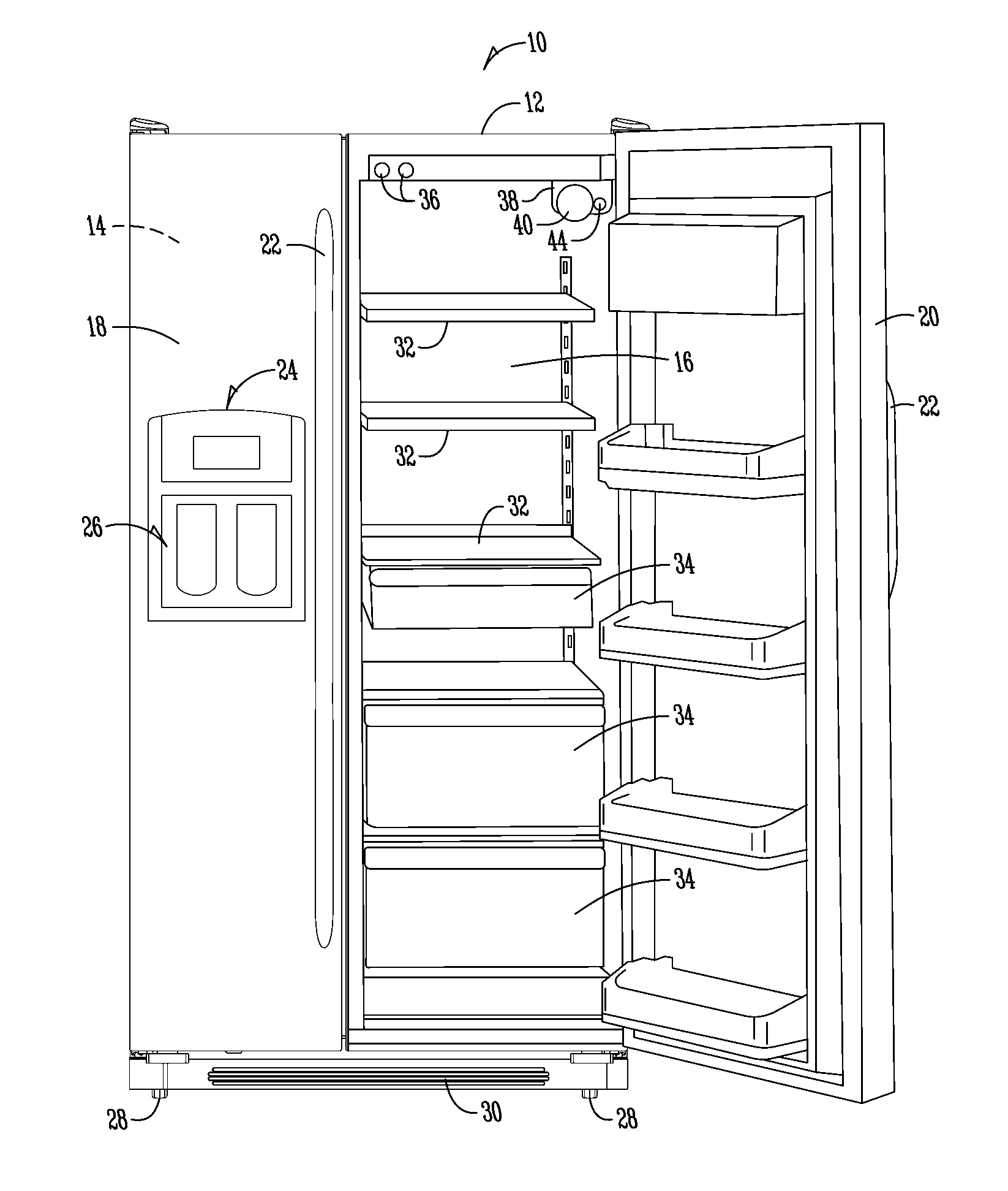
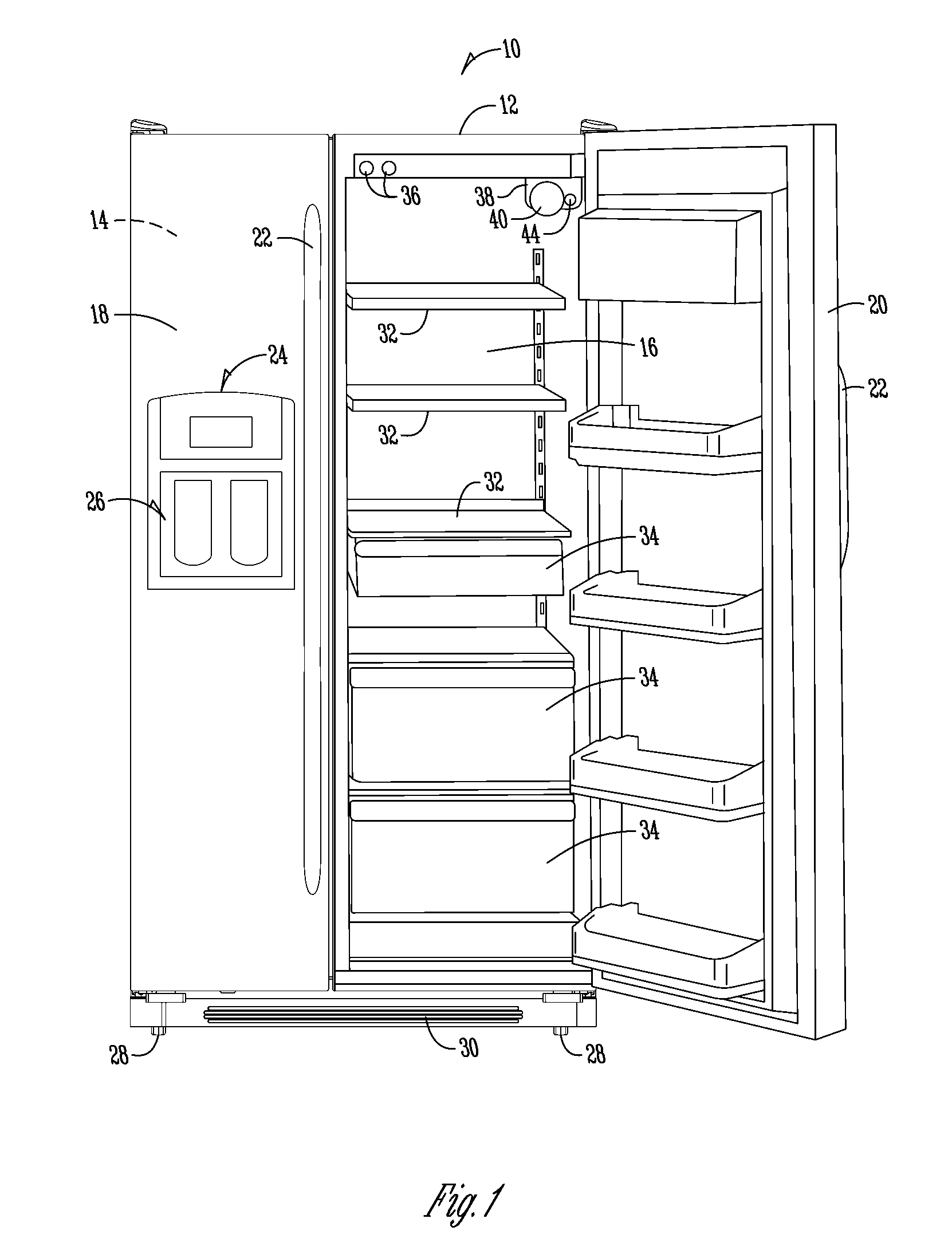
[0020]The present invention includes a number of aspects all of which have broad and far-reaching application. One aspect of the present invention relates to the use of a water reservoir pressure vessel in combination with a water filter of the type as disclosed in U.S. Application Publication No. 2006 / 0081805. Another aspect of the present invention relates to the use of a water reservoir pressure vessel being capable of operating for the life of the refrigeration device by being resistant to fatigue related failures. Another aspect of the present invention relates to the use of a water reservoir pressure vessel being positionable within a preexisting housing and / or the refrigeration device near the exterior dispenser and before the water filter and water solenoid valves to thereby improve the taste of the water being dispensed. Still another aspect of the present invention relates to the construction of a water reservoir pressure vessel from cross-linked, high-density polyethylene...


PUM


Abstract

Refrigeration devices that have a water dispensing system to dispense water to an exterior water dispenser from a water supply line have need of a water vessel for storing water under pressure within the refrigeration device until dispensed. The water vessel has an inlet for receiving water from the water supply line and an outlet for dispensing water to the exterior water dispenser. A plurality of pressure resistant walls are formed between the inlet and the outlet to form an internal volume to reservoir water within the water vessel. The water vessel is constructed to reservoir water within the vessel under hydrostatic pressure from the water supply line until dispensed through the outlet when requested by the exterior water dispenser and/or the icemaker.

Description

CROSS-REFERENCE TO RELATED APPLICATIONS[0001]This application claims priority under 35 U.S.C. §119 of a provisional application Ser. No. 60 / 882,277 filed Dec. 28, 2006, which application is hereby incorporated by reference in its entirety.FIELD OF THE INVENTION[0002]The present invention relates to the field of pressurized water storage vessels; and more particularly, to the field of pressurized water storage vessels for ergonomically and safely reservoiring and chilling water within a refrigeration device for subsequent use.BACKGROUND OF THE INVENTION[0003]Water reservoir vessels or water storage tanks for storing water under pressure are known in the art. Examples of some reservoirs are disclosed in U.S. Pat. Nos. 6,532,758 5,707,518, 3,982,406, and 3,908,394. These water storage tanks have an inlet and an outlet and are generally in fluid communication with a valve or multiple valves, a water inlet and a filter. The tanks vary in shape and design in an attempt to maximize the vol...

Claims


Application Information

Patent Timeline
Patent Type & Authority Applications(United States)
IPC IPC(8): F25D23/12B67D3/00B67D5/62F25D11/00B67D7/80
CPCF25D23/126F25D2323/122F25D2323/121
Inventor MEYERHOLTZ, ERIC R.SHRESTHA, MANOJ K.SMALE, JEFFREY J.LUTZ, LARRY A.
Owner WHIRLPOOL CORP
Why Eureka
Try Eureka