
Device and system for monitoring valves

Inactive Publication Date: 2008-07-03
ROTORK CONTROLS LTD
View PDF14 Cites 60 Cited by
  • Summary
  • Abstract
  • Description
  • Claims
  • Application Information

AI Technical Summary

Benefits of technology

[0018]Other objects and advantages of the present invention will become apparent as the description proceeds.

Problems solved by technology

The use of cables in not only costly to engineer and install, it is also one of the most frequent source of failure in the process line, where a considerable amount of sensors and actuators are moving or exposed to harsh environmental conditions.
Therefore, it is here, at the field device level, where problems with wires really exist for the users.
However, as wires age, they can crack or fail.
Inspecting, testing, troubleshooting, repairing, and replacing wires require significant time, labor, and materials.
If wiring faults cause a production stoppage, costs escalate rapidly.
Although the process operators have a very strong desire and need for monitoring ball valves, in view of the costs and complications involved in the wiring and maintenance, about 80% of the ball valves in industrial facilities remain electronically unmonitored.
However, as said the installation of wired monitor box to monitor the status of each valve is very expensive.
The estimated cost for each monitored wired ball valve is in the range of thousands of US dollars due to the implications to lay wires in a process line facility.
The cost goes even higher when the cables of the ball valve monitoring device pass through ducts, or when they need to be protected by stainless steel coverage.
Sometimes, such a stainless steel coverage protection can increase the costs by 10 times. This is the main result why the industry tends to compromise the rate of monitoring, i.e., by monitoring only a small portion of the ball valves in the facility, generally only those which are considered as critical in the process.

Method used


Image

  • Device and system for monitoring valves
  • Device and system for monitoring valves
  • Device and system for monitoring valves

Examples


Embodiment Construction

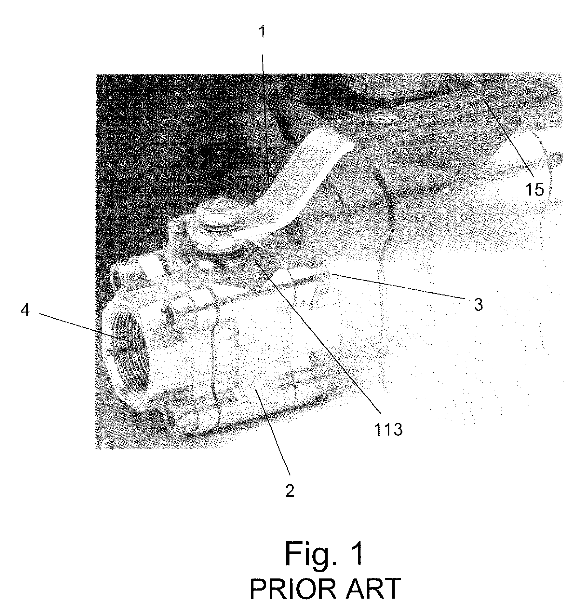
[0051]FIG. 1 shows the structure of a typical ball valve 1, such as widely used in the industry for controlling the flow of fluids. Such typical ball valves are generally sized between ½″ to 4″. The ball valve is installed between two sections of a fluid line, and serves essentially as an OPEN / CLOSE flow switch. The ball valve 1 essentially has a hollow section 2, an inlet 3 and an outlet 4, and a handle 5 for manually opening and closing the valve. As said, the prior art has not yet provided a wireless, and low cost device for monitoring the status of a ball valve, which is reliable, and simple to install and maintain. Moreover, the prior art has not yet provided any wireless means for monitoring a mass number of industrial ball valves, in a manner which is of low cost, simple to install and maintain, and reliable.

[0052]The present invention provides a ball valve monitoring device which solves most of the prior art drawbacks which essentially formed a significant burden for the ind...


PUM


Abstract

The invention relates to a network system for monitoring valves in a facility, which comprises: (a) a plurality of valve monitoring devices—VMDs, each monitoring device is affixed to a valve, and comprises: (a.1) a sensor for sensing the status of the valve; (a.2) short range wireless communication unit for transmitting the status as sensed by said sensor, and for transmitting the status as sensed, together with an identification of said device, to one or more Valve Device Readers—VDRs located within said short range; (a.3) mechanism for affixing the device to the monitored valve in a manner which does not disturb the normal operation of the valve; and (a.4) one or more VDRs for receiving the transmission of the valve status and MD identification from said VMDs, and for forwarding the same to a server by Ethernet communication.

Description

FIELD OF THE INVENTION[0001]The present invention relates to the field of systems and devices for monitoring and / or controlling the flow of fluids, particularly in industrial facilities. More particularly, the invention relates to a system and device for monitoring the status of valves in an industrial facility.BACKGROUND OF THE INVENTION[0002]In today's industrial environment, systems and equipment must perform at levels thought impossible a decade ago. Global competition is forcing industry to continuously improve process operations, product quality, yield and productivity with fewer people than ever before. Production equipment must deliver unprecedented levels of reliability, availability, and maintainability as plant managers seek ways to reduce operational and support costs and to eliminate or minimize capital investments. In short, industry must invoke new measures to improve production performance and safety while minimizing costs and extending the operational life of new an...

Claims


Application Information

Patent Timeline
IPC IPC(8): G01M19/00F16K37/00G01M99/00
CPCF16K37/0083Y10T137/8175Y10T137/8242F16K37/00H04B7/24
Inventor RADOMSKY, ISRAELFUCHS, REUBENKALMAN, ISRAELNEMENOFF, AMIRGAL, OHAD
Owner ROTORK CONTROLS LTD
Learn More