Synthetic Colour Night Vision System

a night vision system and colour technology, applied in the field of synthetic colour night vision system, can solve the problems of reducing resolution, white light loss during transmission through filter, and mediocre night vision color imag

Active Publication Date: 2008-07-03
ELBIT SYST LTD
View PDF10 Cites 37 Cited by
  • Summary
  • Abstract
  • Description
  • Claims
  • Application Information

AI Technical Summary

Problems solved by technology

However, white light is lost during transmission through a filter.
Additionally, many of the aforementioned methods include the use of white phosphors that do not maintain the same brightness as monochrome phosphors.
Brightness reduction and diminished resolution lead to a mediocre night vision color image.
Furthermore, using multiple image intensifying components or sensors, as described above, increases the size of the color night vision system.

Method used


Image

  • Synthetic Colour Night Vision System
  • Synthetic Colour Night Vision System
  • Synthetic Colour Night Vision System

Examples


Embodiment Construction

[0019]In the following detailed description, numerous specific details are set forth in order to provide a thorough understanding of the invention. However, it will be understood by those skilled in the art that the present invention may be practiced without these specific details. In other instances, well-known methods, procedures, and components have not been described in detail so as not to obscure the present invention.

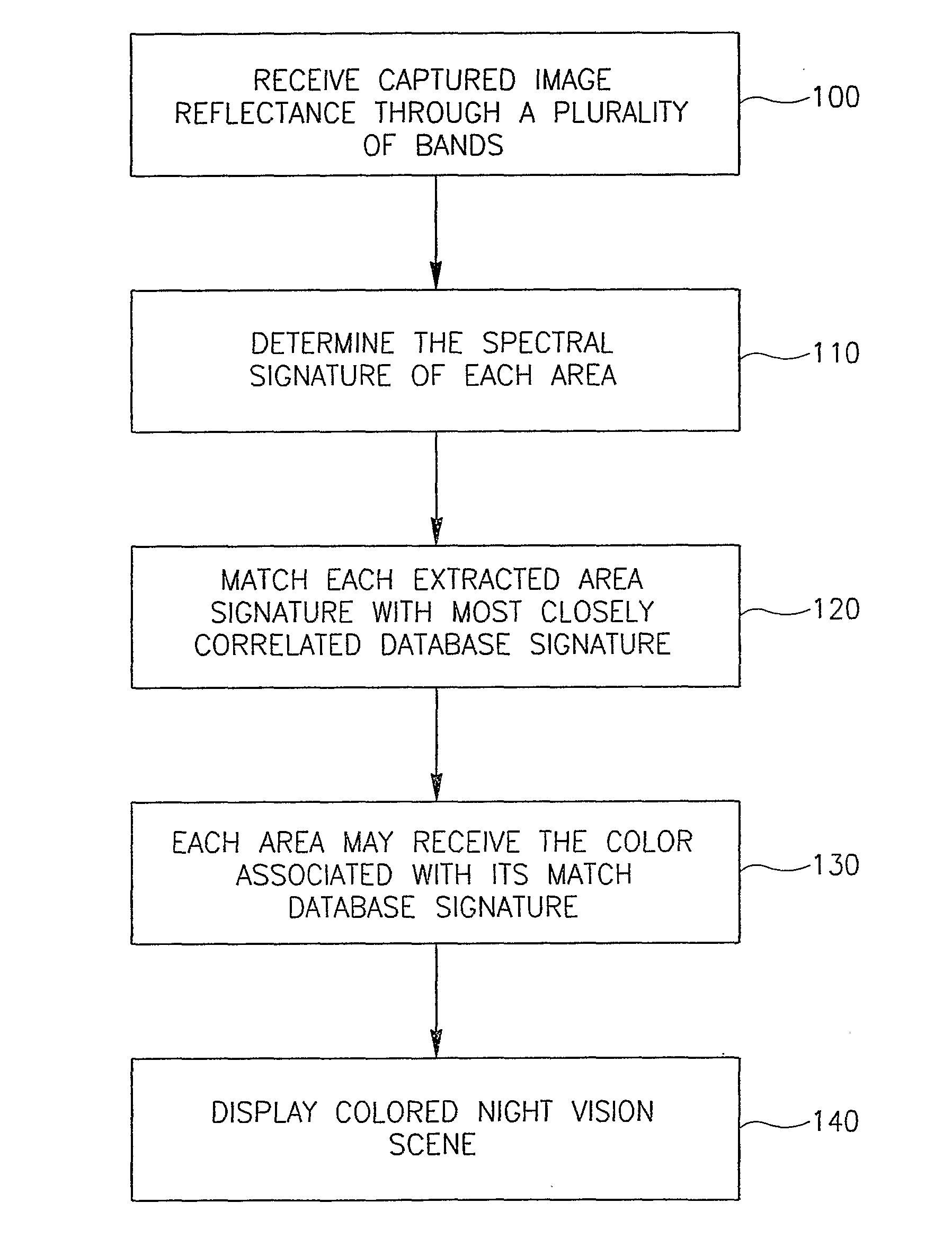
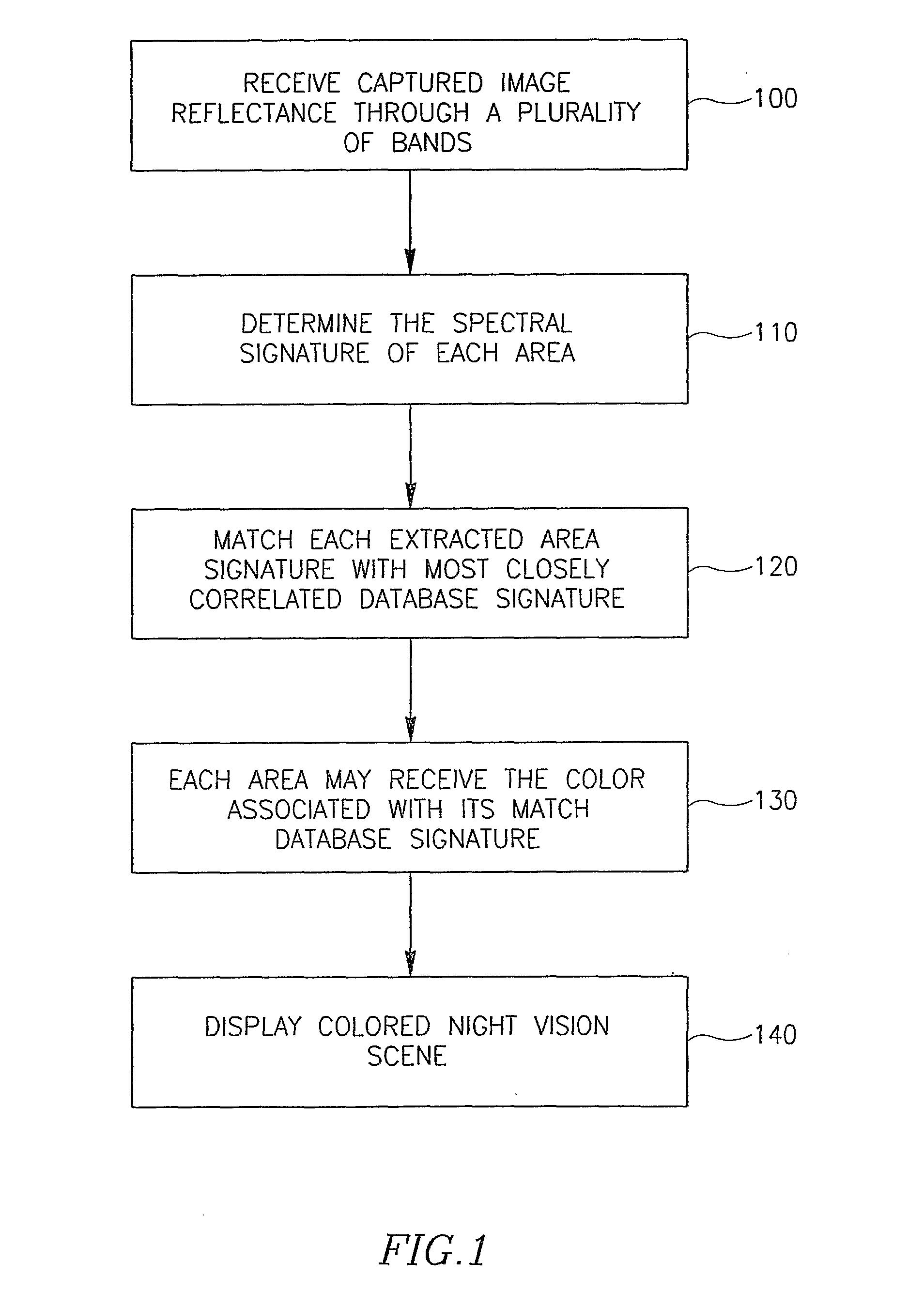
[0020]A method according to an embodiment, shown in FIG. 1, may comprise the determination of the spectral signature of each area in an intensified image reflection (block 110). The spectral signature may be determined by the captured image reflectance through a plurality of bands (block 100). A computer processor may typically match the extracted spectral signature of each area in the intensified reflected image with the most closely correlated database signature (block 120). Each area may receive the color associated with its matched database signature (block 13...


PUM


Abstract

A night vision coloring system may color a scene by extracting the spectral signature of each area in a scene and matching the extracted signature with a predetermined database signature and associated color. The system may comprise a temporal or spatial filtering element that may typically allow the capturing of an image reflection through a plurality of spectral bands, thereby extracting the spectral signature of each area in the image. The color associated with the matched database signature may be used to color each area comprising the image.

Description

BACKGROUND OF THE INVENTION[0001]Conventional night vision systems, e.g. night vision goggles, use the reflected light from an object or scene by intensifying the image reflection and generating a monochrome image. The generated image is represented by monochromatic shades of intensity. More specifically, these types of systems use the image intensifier as an optical amplifier. Emitted photons, due to the illuminated image, that strike the entrance to the intensifier are converted to electrons by a photo-cathode. An electric field applied between the photo-cathode and Micro Channel Plate (MCP) accelerates the electrons. The electric field is also applied through the MCP itself. The electrons are accelerated through the MCP, which amplifies the number of incoming accelerated electrons that ultimately bombard monochrome phosphors on a phosphorous screen. The phosphorous screen converts the amplified electrons back to photons, thereby displaying an amplified image represented by green ...

Claims


Application Information

Patent Timeline
Patent Type & Authority Applications(United States)
IPC IPC(8): G01J1/10
CPCG02B23/12H04N5/332H04N5/33H04N23/11
Inventor SHAMIR, HANANYAELI, YOSIEFRAT, ILAN
Owner ELBIT SYST LTD
Why Eureka
Try Eureka