Vibration motor

a technology of vibration motor and motor, which is applied in the direction of mechanical vibration separation, dynamo-electric machines, electrical apparatus, etc., can solve the problems that the size of the coil 107/b> cannot be increased, and the vibration of the motor cannot be increased either. achieve the effect of increasing the vibration of the motor and reducing the amount of electrical consumption during operation

Inactive Publication Date: 2008-07-03
SAMSUNG ELECTRO MECHANICS CO LTD
View PDF23 Cites 9 Cited by
  • Summary
  • Abstract
  • Description
  • Claims
  • Application Information

AI Technical Summary

Benefits of technology

[0011]A certain aspect of the invention is to provide a vibration motor which can increase the vibration of a motor and reduce the amount of electrical consumption during operation.
[0012]Another aspect of the invention is to provide a vibration motor having a rotor that can be manufactured easily.
[0015]The weight may have a central angle smaller than 180°, and may be made of tungsten or a tungsten alloy. The shaft may be inserted in the case and the base by way of a bearing, for smoother rotation of the shaft. Also, a sliding washer may be positioned between the end of the shaft and the base for an even smoother rotation of the shaft.

Problems solved by technology

However, as illustrated in FIG. 1, since the weight 113 is positioned on the upper portion of the rotor in a conventional coin type vibration motor, the sizes of the coils 107 cannot be increased, and thus the vibration of the motor cannot be increased either.

Method used


Image

  • Vibration motor
  • Vibration motor
  • Vibration motor

Examples


Embodiment Construction

[0023]Embodiments of the invention will be described below in more detail with reference to the accompanying drawings. In the description with reference to the accompanying drawings, those components are rendered the same reference number that are the same or are in correspondence regardless of the figure number, and redundant explanations are omitted.

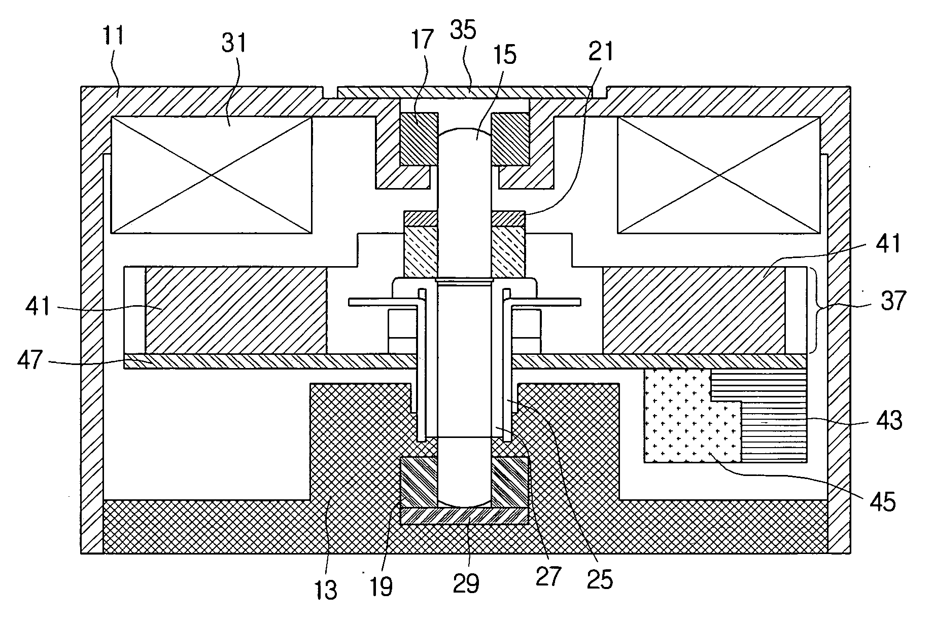
[0024]Referring to FIG. 3, a vibration motor according to an embodiment of the invention includes a base 13 and case 11 which form an internal space, a shaft 15 rotatably inserted in the base 13 and case 11, a rotor 37 which is supported by the shaft 15 and which induces vibration, a weight 43 attached to the lower surface of the rotor 37, brushes 25 which are in contact with the commutator 27 and which are positioned on the base 13, and a magnet 31 which faces the rotor 37 and which is secured to the case 11. The rotor 37 includes wound coils 41 and the weight 43, which may be secured onto a hard board 47 by a mold 45.

[0025]In the vib...


PUM


Abstract

A vibration motor that includes a base and a case which form an internal space, a shaft rotatably inserted in the base and the case, a rotor inserted onto the shaft and configured to rotate, which includes multiple wound coils and a commutator connected to the wound coils, a weight attached to a lower surface of the rotor, a brush which is in contact with the commutator and which is positioned on the base, and a magnet facing the rotor, can increase vibration and reduce electrical consumption during operation.

Description

CROSS-REFERENCE TO RELATED APPLICATIONS[0001]This application claims the benefit of Korean Patent Application No. 2005-0130582 filed with the Korean Intellectual Property Office on Dec. 27, 2005, the disclosure of which is incorporated herein by reference in its entirety.BACKGROUND[0002]1. Technical Field[0003]The present invention relates to a vibration motor.[0004]2. Description of the Related Art[0005]In general, a vibration motor generates vibration as the rotor is rotated while in an eccentric configuration, and such a vibration motor is often manufactured to have a small size for use in a mobile phone or pager, etc.[0006]FIGS. 1 and 2 illustrate a general coin type vibration motor, where FIG. 1 is a plan view of the rotor mold portion formed as a single body with the rotor positioned on the inside upper portion of the vibration motor, and FIG. 2 is a cross-sectional view of a coin type vibration motor incorporating the cross section I-I′ of FIG. 1.[0007]As illustrated in FIGS....

Claims


Application Information

Patent Timeline
Patent Type & Authority Applications(United States)
IPC IPC(8): H02K7/065
CPCH02K7/063H02K7/075H02K23/54B06B1/045H02K15/03
Inventor KI, HYUN-SEUNG
Owner SAMSUNG ELECTRO MECHANICS CO LTD
Why Eureka
Try Eureka