
Post-filter for microphone array

a post-filter and microphone technology, applied in the field of post-filters for microphone arrays, can solve the problems of reducing the reliability of a signal received by a microphone located at a far point, reducing the gsc and zelinski post-filters, and rarely satisfying assumptions in the actual environment, so as to reduce the “musical noise” and reduce the high correlated noise instances. , the effect of reducing the low correlated nois

Inactive Publication Date: 2008-07-03
JAPAN ADVANCED INST OF SCI & TECH +1
View PDF2 Cites 85 Cited by
  • Summary
  • Abstract
  • Description
  • Claims
  • Application Information

AI Technical Summary

Benefits of technology

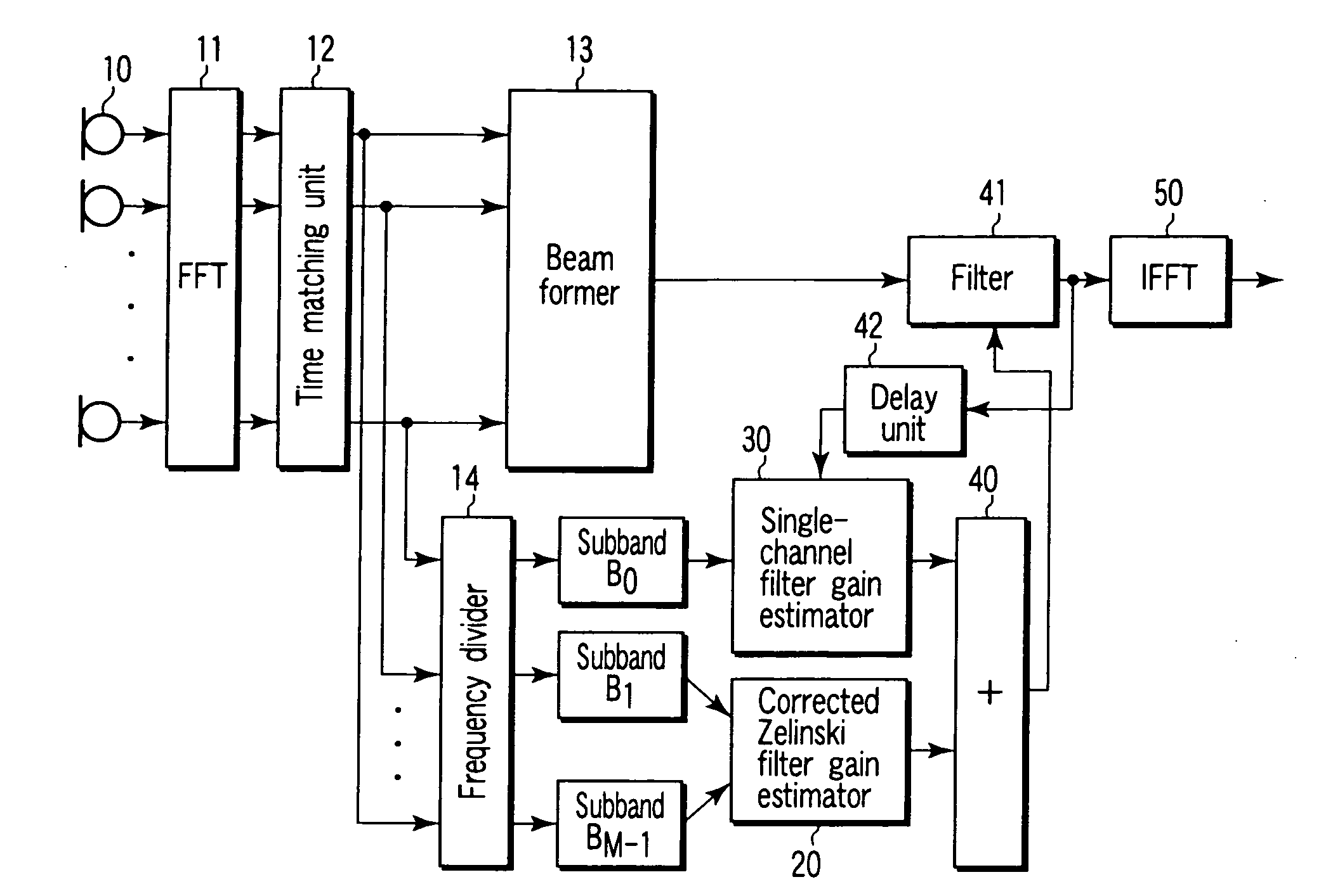
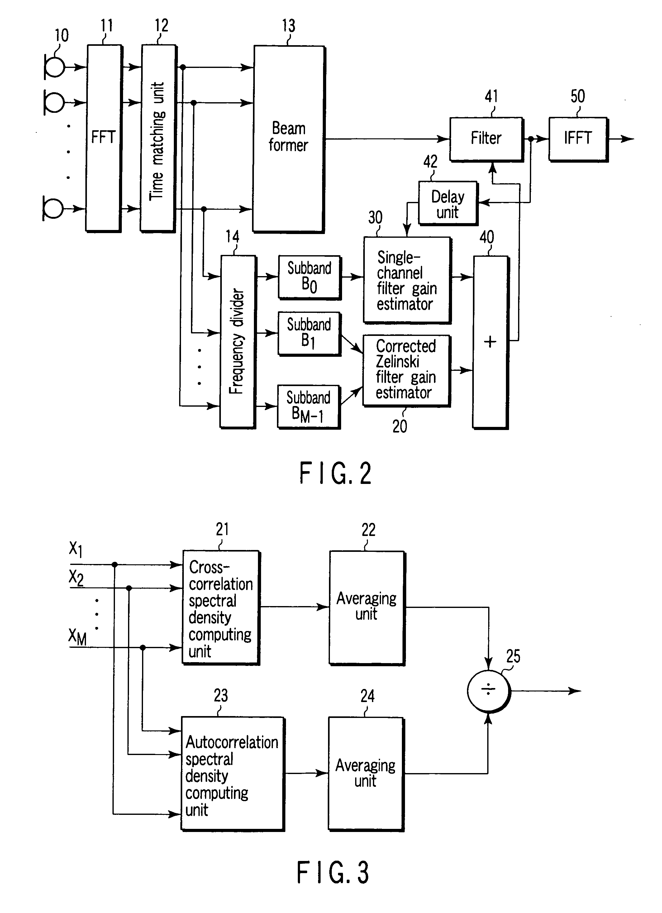
The present invention provides a novel post-filter that can effectively reduce high correlated noise instances and low correlated noise instances in a diffused noise field. The post-filter includes a microphone array, a beam former, a divider, two filters, an adder, and means for reducing noise instances. The technical effect of this invention is to improve the quality of sound signals in practical noise environments, such as reverberated room or vehicle compartments.

Problems solved by technology

One of the critical problems for this technique is that the reliability of a signal received by a microphone located at a far point is extremely reduced by various types of noise.
This assumption, however, is rarely satisfied in the actual environment, or especially, in the case where microphones are located close to each other or in a low-frequency range high in correlation between noise instances.
It is pointed out, however, that both the GSC and the Zelinski post-filter have no satisfactory behavior in the low-frequency area.
Actually, however, the basic assumption of the Zelinski post-filter that the noise instances for the respective microphones are not correlated is rarely satisfied in the practical environment.

Method used


Image

  • Post-filter for microphone array
  • Post-filter for microphone array
  • Post-filter for microphone array

Examples


Embodiment Construction

[0048]An embodiment of the invention will be explained with reference to the drawings. In the description that follows, first, an explanation is given about a coherence function and an application thereof in a model noise field. Then, a hybrid post-filter in a diffused noise field is explained, and finally, the advantages of a post-filter according to the invention are described.

[0049]A complex coherence function defined by the equation below is widely used to characterize the noise field.

[Expression5]Γxixj(k,l)=φxixj(k,l)φxixi(k,l)φxjxj(k,l)(17)

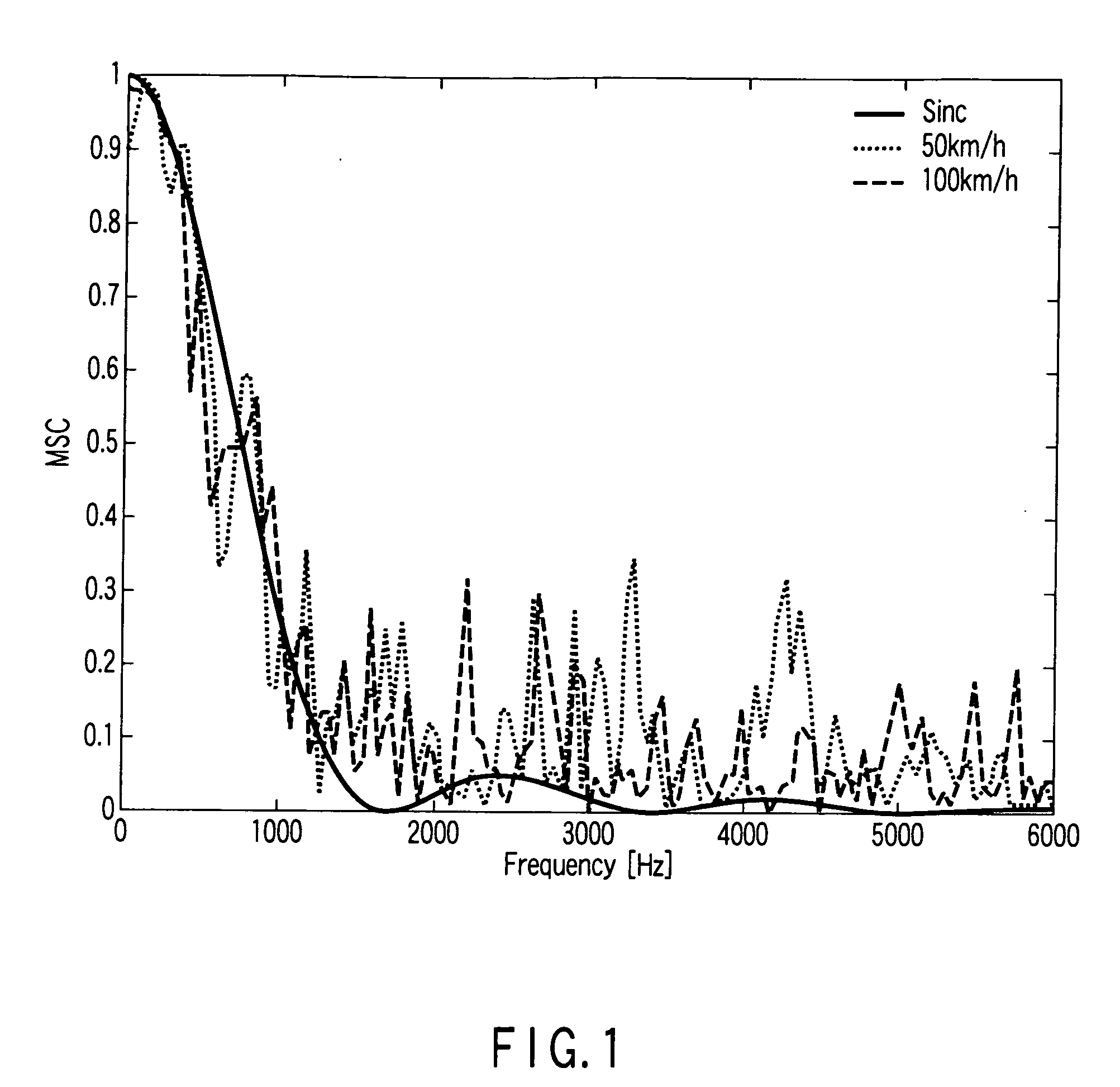
where φxixj(k,l) is a cross-correlation spectral density between two signals xi(t) and xj(t); and φxixi(k,l) and φxjxj(k,l) are autocorrelation spectral densities of the signals xi(t) and xj(t), respectively. A magnitude-squared coherence (MSC) function, which is another important means, is defined as a square of an amplitude of the complex coherence function given by MSC(k,l)=|Γxixj(k,l)|2 used in this specification to analyze the noise fie...


PUM


Abstract

A post-filter includes a microphone array including at least two microphones to which a voice signal are input, a beam former which forms the voice signal input from the microphone array, a divider which divides a target sound containing noise input from the microphone array into at least two frequency bands at a predetermined frequency, a first filter which estimates the filter gain with the noise non-correlated between the microphones, a second filter which estimates a filter gain of one microphone of the microphone array or an average signal of the microphone array, an adder which adds the outputs from the first and second filters to each other, and a filter for reducing the noise based on the outputs from the adder and the beam former.

Description

CROSS-REFERENCE TO RELATED APPLICATIONS[0001]This is a Continuation Application of PCT Application No. PCT / JP2006 / 317229, filed Aug. 31, 2006, which was published under PCT Article 21(2) in Japanese.[0002]This application is based upon and claims the benefit of priority from prior Japanese Patent Application No. 2005-255103, filed Sep. 2, 2005, the entire contents of which are incorporated herein by reference.BACKGROUND OF THE INVENTION[0003]1. Field of the Invention[0004]The present invention relates to a post-filter for a microphone array.[0005]2. Description of the Related Art[0006]Many applications including cell phones and automatic voice recognition systems are desirably based on a hands-free technique due to its utility and flexibility. One of the critical problems for this technique is that the reliability of a signal received by a microphone located at a far point is extremely reduced by various types of noise. As a solution to this problem, the use of a spatial filter havi...

Claims


Application Information

Patent Timeline
Patent Type & Authority Applications(United States)
IPC IPC(8): H04R3/00G10L21/0208G10L21/0232G10L21/0264
CPCG10L21/0208H04R3/005G10L2021/02166
Inventor AKAGI, MASATOLI, JUNFENGUECHI, MASAAKISASAKI, KAZUYA
Owner JAPAN ADVANCED INST OF SCI & TECH
Learn More