

System and method for automated patient anatomy localization
- Summary
- Abstract
- Description
- Claims
- Application Information
AI Technical Summary
Benefits of technology
Problems solved by technology
Method used
Image

Examples
Embodiment Construction
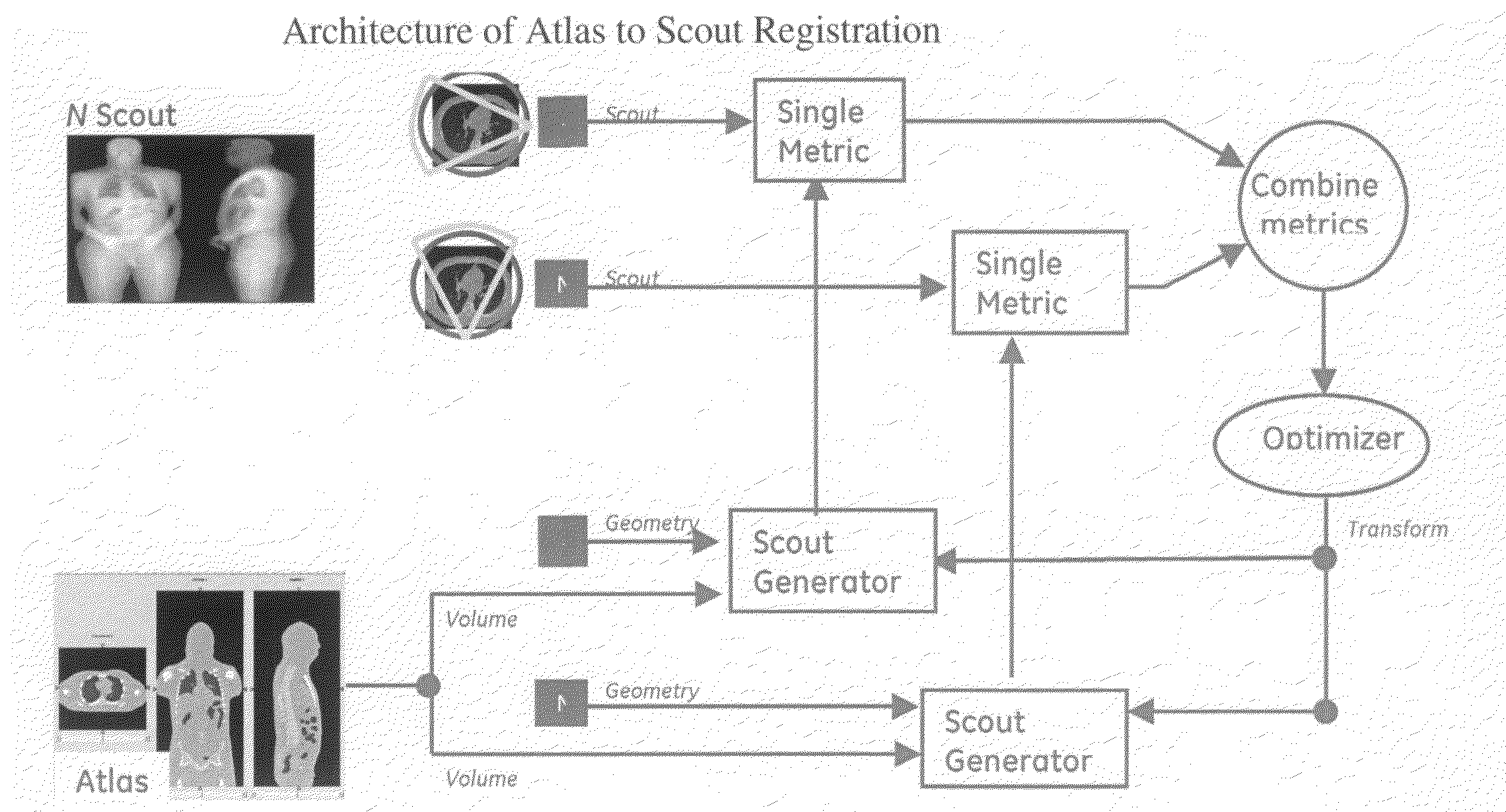
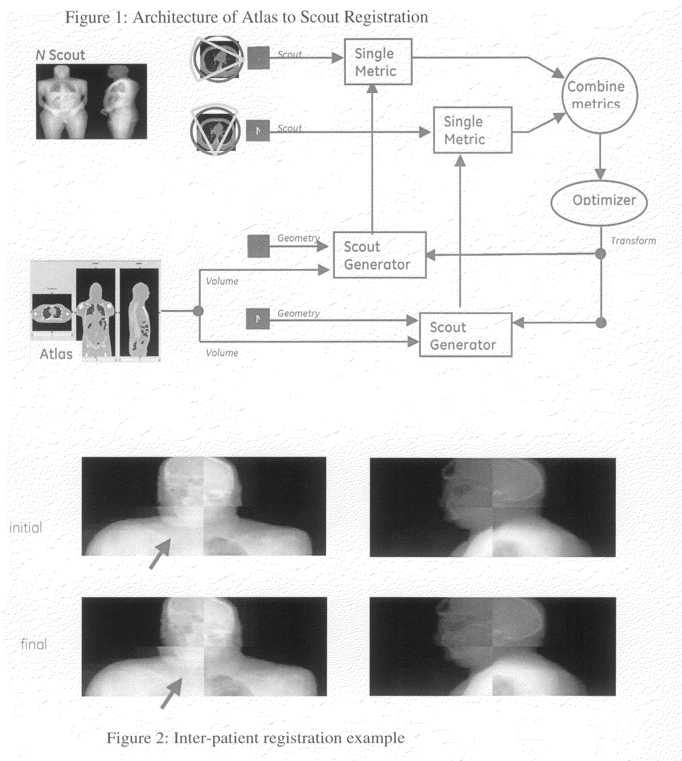
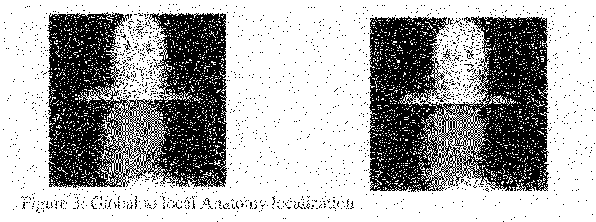
[0012]This invention solves the problem of automatic localization of patient anatomy. This can be done from one or more scout images or from a 3D dataset acquired from a low dose helical “scout”. For example, in a typical CT imaging session, two scout images are acquired first. An operator reviews the scouts and sets scanning parameters to acquire images of patient region of interest. This invention automates this process by automatically finding the patient anatomy from the scout image(s) (2D or 3D). This also allows for automation of the Exam Split process thus improving the workflow and increasing the efficiency.
[0013]In embodiments of the present invention, there is provided a system and method to automatically localize patient anatomy from scout images (one or more 2D scouts or a low dose helical scout) by registering a pre-labeled atlas into the patient space and transforming the atlas labels to find patient anatomy. The system can also recognize the patient orientation. The s...
PUM
 Abstract
Description
Claims
Application Information