Dispersion Compensation Technique for Differential Sonar Measurement - Density Meter.

Active Publication Date: 2013-06-13
CIDRA CORP SERVICES
View PDF2 Cites 2 Cited by
  • Summary
  • Abstract
  • Description
  • Claims
  • Application Information

AI Technical Summary

Benefits of technology

[0019]Some advantages of the present invention include the fact that errors associated with each individual linear fits to separate ridges are eliminat

Problems solved by technology

One of the primary issues with making an accurate SOS measurement is the correction for dispersion

Method used


Image

  • Dispersion Compensation Technique for Differential Sonar Measurement - Density Meter.
  • Dispersion Compensation Technique for Differential Sonar Measurement - Density Meter.
  • Dispersion Compensation Technique for Differential Sonar Measurement - Density Meter.

Examples


Example

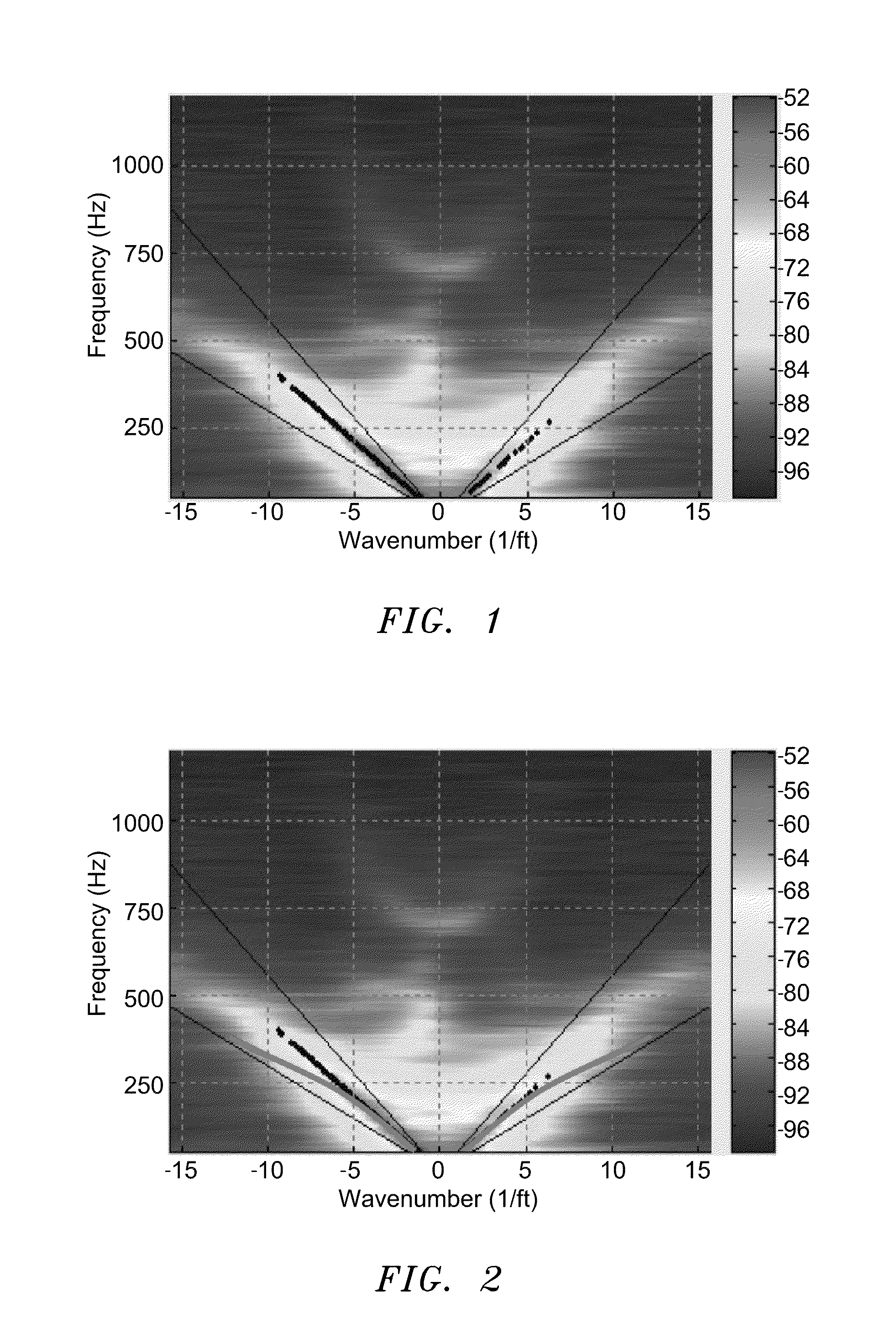
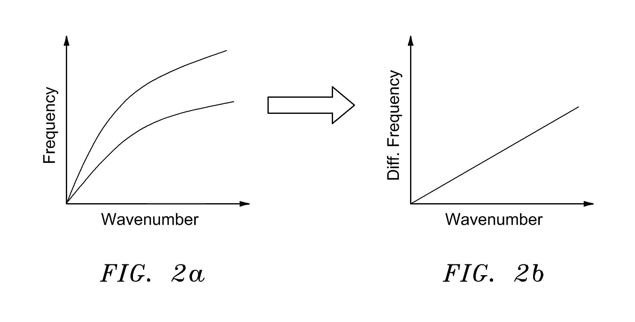
[0031]In summary, the present invention provides a new and accurate technique that can be used to cancel the effects of dispersion when two SOS measurements are required, by processing two sets of data simultaneously and doing a ridge point by point difference. Since the same material is passing through both of the SONAR meters, the dispersion characteristics should be similar, permitting the use of a differential calculation. FIG. 2a shows what the combined processing in k-ω space of two SOS calculations with dispersion. As seen two ridges are present, one from each meter, each with a typical dispersion curve. FIG. 2b shows a straightened differential k-ω plot, after a point by point ridge subtraction is performed in frequency according to the present invention.

[0032]A simple line fit can now be used to calculate the difference in SOS between the two readings. Since this is performed before the final SOS calculation is done, the errors associated with each individual linear fits to...


PUM


Abstract

The present invention provides a novel technique for canceling substantially the effects of dispersion when two speed of sound (SOS) measurements are required on the materials within a pipe to perform a calculation or derive certain characteristics about the materials flowing in the pipe. According to some embodiments of the present invention, the apparatus may comprise a signal processor configured to receive signals containing information about two speed of sound measurements having two sets of data related to materials within a pipe; and process the two sets of data simultaneously and determine a ridge point by point difference in order to cancel substantially effects of dispersion.

Description

CROSS-REFERENCE TO RELATED PATENT APPLICATIONS[0001]The present application claims the benefit of U.S. Provisional Patent Application No. 61 / 312,038, filed 9 Mar. 2010, which is incorporated by reference herein in its entirety.BACKGROUND OF THE INVENTION[0002]1. Technical Field[0003]This invention relates generally to measuring a parameter of a fluid and more particularly to a method and apparatus for measuring a parameter of a fluid such as velocity and volumetric flow rate of the flow within a pipe.[0004]2. Description of Related Art[0005]A fluid flow process (flow process) includes any process that involves the flow of fluid through pipes, ducts, or other conduits, as well as through fluid control devices such as pumps, valves, orifices, heat exchangers, and the like. Flow processes are found in many different industries such as the oil and gas industry, refining, food and beverage industry, chemical and petrochemical industry, pulp and paper industry, power generation, pharmaceu...

Claims


Application Information

Patent Timeline
IPC IPC(8): G01N9/00
CPCG01N9/00G01N9/24G01F1/663G01N2011/0073
Inventor DAVIS, MICHAEL A.
Owner CIDRA CORP SERVICES
Why Eureka
Try Eureka